содержание .. 1398 1399 1400 1401 ..
Nissan X-Trail 32. Manual - part 1400
SYSTEM SETTING
HAC-75
< BASIC INSPECTION >
[AUTOMATIC AIR CONDITIONING]
C
D
E
F
G
H
J
K
L
M
A
B
HAC
N
O
P
• When the battery cable is disconnected from the negative terminal or when the battery voltage is 10 V or
less, the setting for the difference between the set temperature and control temperature is set to the value
stored 1 minute after most recent ignition switch OFF status.
Inlet Port Memory Function (FRE)
INFOID:0000000010939727
DESCRIPTION
• If the ignition switch is turned to the OFF position while the INTAKE switch is set to OFF (fresh air intake),
“Perform the memory” or “Do not perform the memory” of INTAKE switch OFF (fresh air intake) condition can
be selected.
• If “Perform the memory” was set, the INTAKE switch will be OFF (fresh air intake) when turning the ignition
switch to the ON position again.
• If “Do not perform the memory” was set, the air inlets will be controlled automatically when turning the igni-
tion switch to the ON position again.
HOW TO SET
With CONSULT
Perform the “FRE MEMORY SET” of HVAC work support item.
NOTE:
• A/C auto amp. stores the setting at the time 1 minute after the ignition switch turns OFF.
• When the battery cable is disconnected from the negative terminal or when the battery voltage is 10 V or
less, the setting for the difference between the set temperature and control temperature is set to the value
stored 1 minute after most recent ignition switch OFF status.
Setting of Target Evaporator Temperature Upper Limit Value
INFOID:0000000010939728
DESCRIPTION
Setting of upper limit value of target evaporator temperature can be changed. Control characteristic of com-
pressor control (refrigerant discharge amount control) changes according to change of the setting, and then
operation ratio of compressor and refrigerant discharge amount are changed. According to change of the set-
ting, control characteristic focusing on the fuel consumption can be adjusted to control characteristic focusing
on the cooling capacity.
HOW TO SET
With CONSULT
Perform “TARGET EVAPORATOR TEMP UPPER LIMIT SETTING” in “WORK SUPPORT” mode of “HVAC”
using CONSULT.
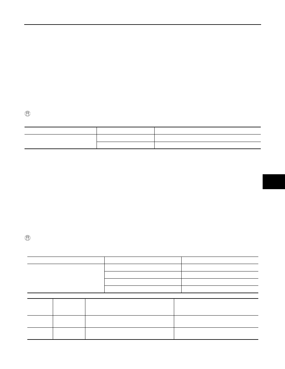
Work support items
Display
Setting
FRE MEMORY SET
WITHOUT (initial status)
Perform the memory of manual FRE
WITH
Do not perform the memory of manual FRE (auto control)
Work support items
Display
Setting
TARGET EVAPORATOR TEMP UPPER
LIMIT SETTING
Initial setting
Initial setting
High
Setting 1
Middle
Setting 2
Low
Setting 3
Setting
Target evapora-
tor temperature
upper limit value
Evaporator freezing protection control
Refrigerant discharge amount control
Initial set-
ting
12
°
C (54
°
F)
Initial setting
Initial setting
Setting 1
7
°
C (45
°
F)
Operation ratio of compressor increases from ini-
tial setting.
Refrigerant discharge amount increases from
initial setting.