содержание .. 135 136 137 138 ..
Nissan X-Trail 32. Manual - part 137
BRC-14
< SYSTEM DESCRIPTION >
[WITH VDC (ESP)]
COMPONENT PARTS
SYSTEM DESCRIPTION
COMPONENT PARTS
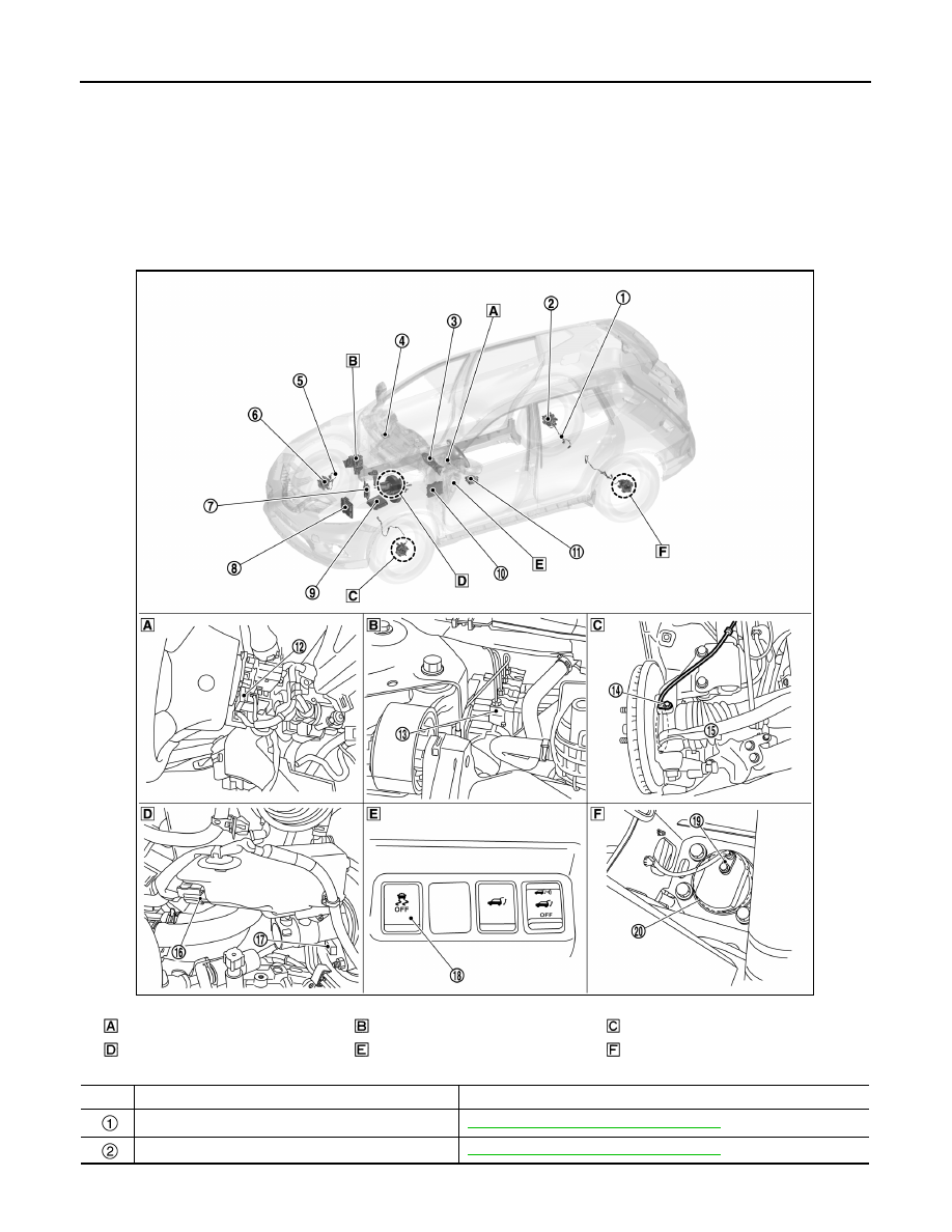
Component Parts Location
INFOID:0000000010723622
LHD
2WD Models
Back of spiral cable assembly
Engine room (RH side)
Steering knuckle
Engine room (LH side)
Instrument driver lower panel
Rear axle housing
No.
Component parts
Function
Rear RH wheel sensor
BRC-27, "Wheel Sensor and Sensor Rotor"
Rear RH sensor rotor
BRC-27, "Wheel Sensor and Sensor Rotor"
JSFIA2501ZZ