Nissan X-Trail 32. Manual - part 1365


  Главная      Nissan     Nissan X-Trail 32 - Service Manual


поиск по сайту            


содержание   ..  1363  1364  1365  1366   ..


Nissan X-Trail 32. Manual - part 1365


REFRIGERATION SYSTEM SYMPTOMS

HA-119

< SYMPTOM DIAGNOSIS >

[QR25DE]

C

D

E

F

G

H

J

K

L

M

A

B

HA

N

O

P

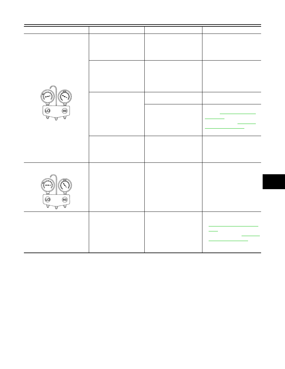
Both high- and low-pressure sides 
are too low.

• The area around evapora-

tor outlet does not become 
cold.

• The area around evapora-

tor inlet becomes frosted.

Clogged expansion valve.
• Breakage of temperature 

sensor.

• Clogging by foreign material.

Eliminate foreign material from 
expansion valve, or replace it.

• There is a temperature dif-

ference between the areas 
around outlet and inlet 
pipes of liquid tank.

• Liquid tank becomes frost-

ed.

Malfunction in inner liquid tank 
(clogged strainer).

Replace condenser.

Evaporator becomes frosted.

Clogged or crushed low-pres-
sure pipe.

Repair or replace malfunction-
ing parts.

Malfunction in intake air tem-
perature sensor.

Check intake sensor system. 
Refer to 

HAC-81, "Diagnosis 

Procedure"

 (AUTOMATIC AIR 

CONDITIONING), 

HAC-192, 

"Diagnosis Procedure"

 (MANU-

AL AIR CONDITIONING).

There is a small temperature 
difference between the high 
and low pressure pipes for re-
frigerant cycle.

• Shortage of refrigerant.
• Leakage of refrigerant.

• Check for leakage.
• Collect all refrigerant, evacu-

ate refrigerant cycle again, 
and then refill it with the spec-
ified amount of refrigerant.

Low-pressure side sometimes be-
comes negative.

• Sometimes the area 

around evaporator outlet 
does not become cold.

• Sometimes the area 

around evaporator inlet is 
frosted.

• Icing caused by the mixing of 

water in cooler cycle.

• Deteriorated dryer in liquid 

tank.

• Collect all refrigerant.
• Evacuate refrigerant cycle 

completely, and then refill it 
with the specified amount of 
refrigerant. At this time, al-
ways replace condenser.

Hunting in high-pressure side.

There is no temperature dif-
ference between high- and 
low-pressure sides.

Malfunctioning variable valve 
in compressor.

• Replace compressor.
• Check ECV system. Refer to 

HAC-113, "Diagnosis Proce-
dure"

 (AUTOMATIC AIR 

CONDITIONING), 

HAC-212, 

"Diagnosis Procedure"


(MANUAL AIR CONDITION-
ING).

Gauge indication

Refrigerant cycle

Probable cause

Corrective action

AC353A

AC354A

HA-120

< SYMPTOM DIAGNOSIS >

[QR25DE]

NOISE

NOISE

Symptom Table

INFOID:0000000011006118

Symptom

Noise source

Probable cause

Corrective action

Unusual noise from compressor 
when A/C is ON.

Inside of compressor

Wear, breakage, or clogging of foreign 
material in inner parts.

Check compressor oil. Re-
fer to 

HA-113, "Inspection"

.

Magnet clutch

Contact of clutch disc with pulley.

Check clearance between 
clutch disc and pulley. Refer 
to 

HA-122, "Inspection"

.

Compressor body

Loosened compressor mounting bolts.

Check bolts for tightness. 
Refer to 

HA-121, "Exploded 

View"

.

Unusual noise from cooler piping.

Cooler piping (pipe and 
flexible hose)

Improper installation of clip and brack-
et.

Check the installation condi-
tion of the cooler piping. Re-
fer to 

HA-123, "Exploded 

View"

.

Unusual noise from expansion 
valve when A/C is ON.

Expansion valve

Shortage of refrigerant.

• Check for leakage.
• Collect all refrigerant, 

evacuate refrigerant cycle 
again, and then refill it 
with the specified amount 
of refrigerant.

Wear, breakage, or clogging of foreign 
material in inner parts.

Eliminate foreign material 
from expansion valve, or re-
place it.

Unusual noise from belt.

Loosened belt

Check belt tension. Refer to  

EM-275, "Drive belt"

.

Internal compressor parts get locked

Replace compressor.

COMPRESSOR

HA-121

< REMOVAL AND INSTALLATION >

[QR25DE]

C

D

E

F

G

H

J

K

L

M

A

B

HA

N

O

P

REMOVAL AND INSTALLATION

COMPRESSOR

Exploded View

INFOID:0000000011006119

Removal and Installation

INFOID:0000000011006120

CAUTION:

Perform lubricant return operation before each refrigeration system disassembly. However, if a large
amount of refrigerant or lubricant is detected, never perform lubricant return operation. Refer to 

HA-

113, "Perform Lubricant Return Operation"

.

REMOVAL

1.

Use a refrigerant collecting equipment (for HFC-134a) to discharge the refrigerant. Refer to 

HA-111,

"Recycle Refrigerant"

.

2.

Remove auto-tensioner. Refer to 

EM-173, "Removal and Installation"

.

3.

Remove mounting bolt 

, and then disconnect low-pressure

flexible hose 

 from compressor.

CAUTION:

Cap or wrap the joint of the A/C piping and compressor with
suitable material such as vinyl tape to avoid the entry of air.

Compressor

: N·m (kg-m, ft-lb)

JSIIA1976GB

: Vehicle front

JMIIA3324ZZ

HA-122

< REMOVAL AND INSTALLATION >

[QR25DE]

COMPRESSOR

4.

Remove mounting bolt 

, and then disconnect high-pressure

flexible hose 

 from compressor.

CAUTION:

Cap or wrap the joint of the A/C piping and compressor with
suitable material such as vinyl tape to avoid the entry of air.

5.

Disconnect harness connector and remove mounting bolts, and then remove compressor.

INSTALLATION

Note the following items, and then install in the reverse order of removal.

CAUTION:

• Replace O-rings with new ones. Then apply compressor oil to them when installing.
• Check for leakages when recharging refrigerant.
• Check tension of the drive belt after installing compressor. Refer to 

EM-167, "Adjustment"

.

Inspection

INFOID:0000000011006122

CHECK DISC TO PULLEY CLEARANCE

Check the clearance (B) between pulley assembly 

 and clutch disc

 along the entire periphery with a feeler gauge (A).

CAUTION:

Replace compressor if specified clearance is not obtained,
replace adjusting spacer and readjust.

: Vehicle front

JMIIA3325ZZ

Clearance

: Refer to 

HA-139, "Compressor"

.

SJIA1918E


содержание   ..  1363  1364  1365  1366   ..