Nissan X-Trail 32. Manual - part 1337


  Главная      Nissan     Nissan X-Trail 32 - Service Manual


поиск по сайту            


содержание   ..  1335  1336  1337  1338   ..


Nissan X-Trail 32. Manual - part 1337


PRECAUTIONS

HA-7

< PRECAUTION >

[R9M (EXCEPT FOR RUSSIA)]

C

D

E

F

G

H

J

K

L

M

A

B

HA

N

O

P

• The auto acc function is adapted to this vehicle. For this reason, even when the ignition switch is turned

to OFF position, the accessory power source does not turned OFF and continues to be supplied for a
certain amount of time.

6.

Disconnect both battery cables. The steering lock will remain released with both battery cables discon-
nected and the steering wheel can be turned.

7.

Perform the necessary repair operation.

8.

When the repair work is completed, re-connect both battery cables. With the brake pedal released, turn
the ignition switch from OFF position to ON position, then to LOCK position. (The steering wheel will lock
when the ignition switch is turned to LOCK position.)

9.

Perform self-diagnosis check of all control units using CONSULT.

Precaution for Procedure without Cowl Top Cover

INFOID:0000000010999963

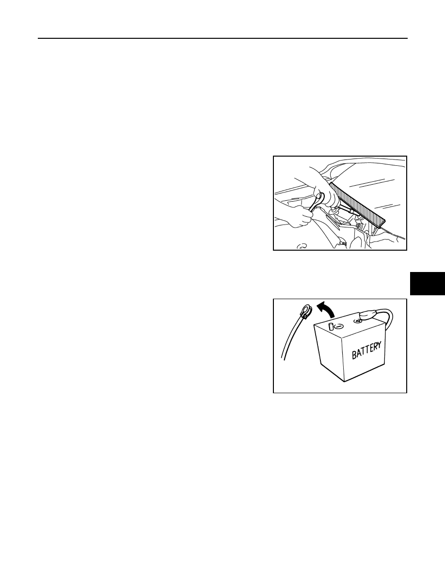
When performing the procedure after removing cowl top cover, cover
the lower end of windshield with urethane, etc to prevent damage to
windshield.

Precautions for Removing Battery Terminal

INFOID:0000000010999964

• With the adoption of Auto ACC function, ACC power is automatically supplied by operating the intelligent key

or remote keyless entry or by opening/closing the driver side door. In addition, ACC power is supplied even
after the ignition switch is turned to the OFF position, i.e. ACC power is supplied for a certain fixed time.

• When disconnecting the 12V battery terminal, turn off the ACC

power before disconnecting the 12V battery terminal, observing
“How to disconnect 12V battery terminal” described below.
NOTE:
Some ECUs operate for a certain fixed time even after ignition
switch is turned OFF and ignition power supply is stopped. If the
battery terminal is disconnected before ECU stops, accidental DTC
detection or ECU data damage may occur.

•  For vehicles with the 2-batteries, be sure to connect the main bat-

tery and the sub battery before turning ON the ignition switch.
NOTE:
If the ignition switch is turned ON with any one of the terminals of
main battery and sub battery disconnected, then DTC may be detected.

•  After installing the 12V battery, always check "Self Diagnosis Result" of all ECUs and erase DTC.

NOTE:
The removal of 12V battery may cause a DTC detection error.

HOW TO DISCONNECT 12V BATTERY TERMINAL

Disconnect 12V battery terminal according to Instruction 1 or Instruction 2 described below.
For vehicles parked by ignition switch OFF, refer to Instruction 2.

INSTRUCTION 1

1.

Open the hood.

2.

Turn key switch to the OFF position with the driver side door opened.

3.

Get out of the vehicle and close the driver side door.

4.

Wait at least 3 minutes. For vehicle with the engine listed below, remove the battery terminal after a lapse
of the specified time.

PIIB3706J

SEF289H

D4D engine

: 20 minutes

HRA2DDT

: 12 minutes

HA-8

< PRECAUTION >

[R9M (EXCEPT FOR RUSSIA)]

PRECAUTIONS

CAUTION:

While waiting, never operate the vehicle such as locking, opening, and closing doors. Violation of
this caution results in the activation of ACC power supply according to the Auto ACC function.

5.

Remove 12V battery terminal.

CAUTION:

After installing 12V battery, always check self-diagnosis results of all ECUs and erase DTC.

INSTRUCTION 2 (FOR VEHICLES PARKED BY IGNITION SWITCH OFF)

1.

Unlock the door with intelligent key or remote keyless entry.
NOTE:
At this moment, ACC power is supplied.

2.

Open the driver side door.

3.

Open the hood.

4.

Close the driver side door.

5.

Wait at least 3 minutes.

CAUTION:

While waiting, never operate the vehicle such as locking, opening, and closing doors. Violation of
this caution results in the activation of ACC power supply according to the Auto ACC function.

6.

Remove 12V battery terminal.

CAUTION:

After installing 12V battery, always check self-diagnosis results of all ECUs and erase DTC.

Precautions For Refrigerant System Service

INFOID:0000000010999965

GENERAL REFRIGERANT PRECAUTION

WARNING:

• Never breathe A/C refrigerant and lubricant vapor or mist. Exposure may irritate eyes, nose and

throat. Remove HFO-1234yf (R-1234yf) from the A/C system, using certified service equipment meet-
ing requirements of SAE J-2843 [HFO-1234yf (R-1234yf) Recovery/Recycling/Recharging Equipment
for Flammable Refrigerants for Mobile Air Conditioning Systems]. Ventilate work area before resum-
ing service if accidental system discharge occurs. Additional health and safety information may be
obtained from refrigerant and lubricant manufacturers.

• Never release refrigerant into the air. Use approved recovery/recycling recharging equipment to cap-

ture the refrigerant each time an air conditioning system is discharged.

• Wear always eye and hand protection (goggles and gloves) when working with any refrigerant or air

conditioning system.

• Never store or heat refrigerant containers above 52

°

C (126

°

F).

• Never heat a refrigerant container with an open flame; Place the bottom of the container in a warm

pail of water if container warming is required.

• Never intentionally drop, puncture, or incinerate refrigerant containers.
• Keep refrigerant away from open flames: poisonous gas is produced if refrigerant burns.
• Refrigerant displaces oxygen, therefore be certain to work in well ventilated areas to prevent suffo-

cation.

• Never pressure test or leakage test HFO-1234yf (R-1234yf) service equipment and/or vehicle air con-

ditioning systems with compressed air during repair. Some mixtures of air and HFO-1234yf (R-
1234yf) have been shown to be combustible at elevated pressures. These mixtures, if ignited, may
cause injury or property damage. Additional health and safety information may be obtained from
refrigerant manufacturers.

WORKING WITH HFO-1234yf (R-1234yf)

CAUTION:

• CFC-12 (R-12) or HFC-134a (R-134a) refrigerant and HFO-1234yf (R-1234yf) refrigerant are not com-

patible. Compressor malfunction is likely to occur if the refrigerants are mixed, refer to “CONTAMI-
NATED REFRIGERANT” below. To determine the purity of HFO-1234yf (R-1234yf) in the vehicle and
recovery tank, use Refrigerant recovery/recycling recharging equipment and Refrigerant Identifier.

K9K engine

: 4 minutes

M9R engine

: 4 minutes

R9M engine

: 4 minutes

V9X engine

: 4 minutes

PRECAUTIONS

HA-9

< PRECAUTION >

[R9M (EXCEPT FOR RUSSIA)]

C

D

E

F

G

H

J

K

L

M

A

B

HA

N

O

P

• Use only specified lubricant for the HFO-1234yf (R-1234yf) A/C system and HFO-1234yf (R-1234yf)

components. Compressor malfunction is likely to occur if lubricant other than that specified is used.

• The specified HFO-1234yf (R-1234yf) lubricant rapidly absorbs moisture from the atmosphere. The

following handling precautions must be observed:

- Cap (seal) immediately the component to minimize the entry of moisture from the atmosphere when

removing refrigerant components from a vehicle.

- Never remove the caps (unseal) until just before connecting the components when installing refrig-

erant components to a vehicle. Connect all refrigerant loop components as quickly as possible to
minimize the entry of moisture into system.

- Use only the specified lubricant from a sealed container. Reseal immediately containers of lubricant.

Lubricant becomes moisture saturated and should not be used without proper sealing.

- Never allow lubricant (ND-OIL 12) to come in contact with styrene foam parts. Damage may result.

CONTAMINATED REFRIGERANT

Take appropriate steps shown below if a refrigerant other than pure HFO-1234yf (R-1234yf) is identi-
fied in a vehicle:
• Explain to the customer that environmental regulations prohibit the release of contaminated refrigerant into

the atmosphere.

• Explain that recovery of the contaminated refrigerant could damage service equipment and refrigerant sup-

ply.

• Suggest the customer return the vehicle to the location of previous service where the contamination may

have occurred.

• In case of repairing, recover the refrigerant using only dedicated equipment and containers. Never

recover contaminated refrigerant into the existing service equipment. Contact a local refrigerant prod-
uct retailer for available service if the facility does not have dedicated recovery equipment. This refrigerant
must be disposed of in accordance with all federal and local regulations. In addition, replacement of all
refrigerant system components on the vehicle is recommended.

• The air conditioner warranty is void if the vehicle is within the warranty period. Please contact Nissan Cus-

tomer Affairs for further assistance.

REFRIGERANT CONNECTION

A new type refrigerant connection has been introduced to all refrigerant lines except the following location.
• Expansion valve to evaporator
• Refrigerant pressure sensor to high-pressure pipe 1

WARNING:

Check that all refrigerant is discharged into the recycling equipment and the pressure in the system is
less than atmospheric pressure. Then gradually loosen the discharge side hose fitting and remove it.

CAUTION:

Observe the following when replacing or cleaning refrigerant cycle components.
• Store it in the same way at it is when mounted on the car when the compressor is removed. Failure

to do so will cause lubricant to enter the low-pressure chamber.

• Use always a torque wrench and a back-up wrench when connecting tubes.
• Plug immediately all openings to prevent entry of dust and moisture after disconnecting tubes.
• Connect the pipes at the final stage of the operation when installing an air conditioner in the vehicle.

Never remove the seal caps of pipes and other components until just before required for connection.

• Allow components stored in cool areas to warm to working area temperature before removing seal

caps. This prevents condensation from forming inside A/C components.

• Remove thoroughly moisture from the refrigeration system before charging the refrigerant.
• Replace always used O-rings.
• Apply lubricant to circle of the O-rings shown in illustration when connecting tube. Be careful not to

apply lubricant to threaded portion.

• O-ring must be closely attached to the groove portion of tube.
• Never damage O-ring and tube when replacing the O-ring.
• Connect tube until a click can be heard. Then tighten the nut or bolt by hand. Check that the O-ring is

installed to tube correctly.

Name

: ND-OIL12

HA-10

< PRECAUTION >

[R9M (EXCEPT FOR RUSSIA)]

PRECAUTIONS

• Perform leakage test and make sure that there is no leakage from connections after connecting line.

Disconnect that line and replace the O-ring when the refrigerant leaking point is found. Then tighten
connections of seal seat to the specified torque.

COMPRESSOR

CAUTION:

• Plug all openings to prevent moisture and foreign matter from entering.
• Store it in the same way at it is when mounted on the car when the compressor is removed.
• Follow “Maintenance of Lubricant Quantity in Compressor” exactly when replacing or repairing

compressor. Refer to 

HA-22, "Description"

.

• Keep friction surfaces between clutch and pulley clean. Wipe it off by using a clean waste cloth

moistened with thinner if the surface is contaminated with lubricant.

• Turn the compressor shaft by hand more than five turns in both directions after compressor service

operation. This distributes equally lubricant inside the compressor. Let the engine idle and operate
the compressor for one hour after the compressor is installed.

• Apply voltage to the new one and check for normal operation after replacing the compressor magnet

clutch.

Service Equipment

INFOID:0000000010999966

RECOVERY/RECYCLING RECHARGING EQUIPMENT

Be certain to follow the manufacturer’s instructions for machine operation and machine maintenance. Never
introduce any refrigerant other than that specified into the machine.

ELECTRICAL LEAK DETECTOR

Be certain to follow the manufacturer’s instructions for tester operation and tester maintenance.

VACUUM PUMP

RHA861F


содержание   ..  1335  1336  1337  1338   ..