Nissan X-Trail 32. Manual - part 133


  Главная      Nissan     Nissan X-Trail 32 - Service Manual


поиск по сайту            


содержание   ..  131  132  133  134   ..


Nissan X-Trail 32. Manual - part 133


BR-126

< REMOVAL AND INSTALLATION >

[RHD]

REAR DISC BRAKE

3.

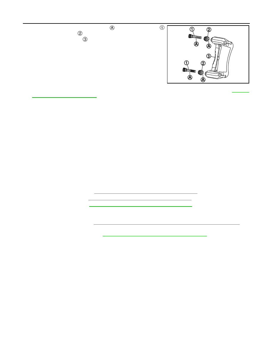
Apply rubber grease to mating faces 

 between sliding pins 

and sliding pin boots 

, and install sliding pins and sliding pin

boots to torque member 

.

4.

Install the cylinder body to tighten cylinder body mounting bolts to the specified torque. Refer to 

BR-120,

"BRAKE PAD : Exploded View"

.

BRAKE CALIPER ASSEMBLY : Inspection and Adjustment

INFOID:0000000010838982

INSPECTION AFTER DISASSEMBLY

Check the following items and replace if necessary.

Cylinder Body

Check the cylinder inner wall for rust, wear, cracks or damage.

CAUTION:

Always clean with new brake fluid. Never clean with mineral oil such as gasoline and light oil.

Torque Member

Check the torque member for rust, wear, cracks or damage.

Sliding Pin, Sliding Pin Boot and Bushing

Check the sliding pins, sliding pin boots and bushing for rust, wear, cracks or damage.

INSPECTION AFTER INSTALLATION

• Check a drag of rear disc brake. If any drag is found, follow the procedure described below.

1.

Remove brake pads. Refer to 

BR-120, "BRAKE PAD : Removal and Installation"

.

2.

Press the pistons. Refer to 

BR-120, "BRAKE PAD : Removal and Installation"

.

3.

Install brake pads. Refer to 

BR-120, "BRAKE PAD : Removal and Installation"

.

4.

Depress the brake pedal several times.

5.

Check a drag of rear disc brake again. When any drag is found, disassemble the cylinder body and
replace if necessary. Refer to 

BR-125, "BRAKE CALIPER ASSEMBLY : Disassembly and Assembly"

.

• Burnish contact surfaces brake pads and disc rotor after refinishing or replacing disc rotor, or if a soft pedal

occurs at very low mileage. Refer to 

BR-83, "BRAKE PAD : Inspection and Adjustment"

.

JPFIA0837ZZ

SERVICE DATA AND SPECIFICATIONS (SDS)

BR-127

< SERVICE DATA AND SPECIFICATIONS (SDS) 

[RHD]

C

D

E

G

H

I

J

K

L

M

A

B

BR

N

O

P

SERVICE DATA AND SPECIFICATIONS (SDS)

SERVICE DATA AND SPECIFICATIONS (SDS)

General Specifications

INFOID:0000000010930899

Unit: mm (in)

Brake Pedal

INFOID:0000000010838623

Unit: mm (in)

Brake Booster

INFOID:0000000010838624

Unit: mm (in)

Front Disc Brake

INFOID:0000000010930900

Unit: mm (in)

Front brake

Caliper type

1 piston type

2 piston type

Cylinder bore diameter

60.33 (2.3752)

44.45 

×

 2 (1.7500 

×

 2)

Pad length 

×

 width 

×

 thickness

123.6 

×

 47.5 

×

 10.5 (4.87 

×

 1.870 

×


0.413)

133.6 

×

 48.5 

×

 10.0 (5.26 

×

 1.909 

×


0.39)

Rotor outer diameter 

×

 thickness

296 

×

 26.0 (11.65 

×

 1.024)

320 

×

 28.0 (12.60 

×

 1.102)

Rear brake 

Cylinder bore diameter

38.2 (1.504)

Pad length 

×

 width 

×

 thickness

82.9 

×

 39.8 

×

 9.0 (3.263 

×

 1.567 

×

 0.354)

Rotor outer diameter 

×

 thickness

292 

×

 16.0 (11.50 

×

 0.630)

Master cylinder

Cylinder bore diameter

23.81 (0.9374)

Control valve

Valve type

Electric brake force distribution

Brake booster

Diaphragm diameter

250 (0.9374)

Recommended brake fluid

Refer to 

MA-23, "Fluids and Lubricants"

.

Item

Standard

Brake pedal height

175.0 – 185.0 (6.89 – 7.28)

Depressed brake pedal height
[Depressing 490 N (50 kg, 110 lb) while turning the engine ON]

85.0 (3.35) or more

Clearance between stop lamp switch and brake pedal position switch (with ASCD) threaded 
end and the brake pedal lever

0.20 – 1.96 (0.0079 – 0.0772)

Brake pedal play

3 – 11 (0.12 – 0.43)

Item

Standard

Input rod length

124.25 – 125.75 (4.89 – 4.95)

Item

Limit

Brake caliper type

1 piston type

2 piston type

Brake pad

Wear thickness

2.0 (0.079)

2.0 (0.079)

Disc rotor

Wear thickness

24.0 (0.945)

26.0 (1.0236)

Thickness variation (measured at 8 positions)

0.020 (0.0008)

0.020 (0.0008)

Runout (with it attached to the vehicle)

0.035 (0.0014)

0.035 (0.0014)

BR-128

< SERVICE DATA AND SPECIFICATIONS (SDS) 

[RHD]

SERVICE DATA AND SPECIFICATIONS (SDS)

Rear Disc Brake

INFOID:0000000010930901

Unit: mm (in)

Item

Limit

Brake pad

Wear thickness

2.0 (0.079)

Disc rotor

Wear thickness

14.0 (0.551)

Thickness variation (measured at 8 positions)

0.020 (0.0008)

Runout (with it attached to the vehicle)

0.070 (0.0028)

BRC-1

BRAKES

C

D

E

G

H

I

J

K

L

M

SECTION 

BRC

A

B

BRC

N

O

P

CONTENTS

BRAKE CONTROL SYSTEM

WITH VDC (ESP)

HOW TO USE THIS MANUAL ......................

7

HOW TO USE THIS SECTION ............................

7

Information ................................................................

7

PRECAUTION ...............................................

8

PRECAUTIONS ...................................................

8

Precaution for Supplemental Restraint System 
(SRS) "AIR BAG" and "SEAT BELT PRE-TEN-
SIONER" .................................................................
..

8

Precaution Necessary for Steering Wheel Rota-
tion After Battery Disconnect ...................................
..

8

Precautions for Removing Battery Terminal  .............

9

Precaution for Procedure without Cowl Top Cover 

....

10

Precaution for Stop/Start System Service ...............

10

Precautions for Harness Repair  ..............................

10

Precaution for Brake System  ..................................

11

Precaution for Brake Control System ......................

11

SYSTEM DESCRIPTION  .............................

14

COMPONENT PARTS  .......................................

14

Component Parts Location ......................................

14

ABS Actuator and Electric Unit (Control Unit)  .........

25

Wheel Sensor and Sensor Rotor  ............................

27

Steering Angle Sensor  ............................................

27

VDC (ESP) OFF Switch  ..........................................

28

hill descent control (Downhill Drive Support) 
Switch ......................................................................

28

Brake Fluid Level Switch .........................................

28

Brake Vacuum Sensor  ............................................

29

SYSTEM .............................................................

30

System Description  .................................................

30

Circuit Diagram  .......................................................

43

Fail-Safe ..................................................................

43

VDC (ESP) FUNCTION  .............................................

48

VDC (ESP) FUNCTION : System Description  ........

48

TCS FUNCTION .........................................................

51

TCS FUNCTION : System Description ....................

52

ABS FUNCTION  ........................................................

53

ABS FUNCTION : System Description ....................

53

EBD FUNCTION  ........................................................

55

EBD FUNCTION : System Description ....................

55

BRAKE LIMITED SLIP DIFFERENTIAL (BLSD) 
FUNCTION .................................................................

56

BRAKE LIMITED SLIP DIFFERENTIAL (BLSD) 
FUNCTION : System Description  ............................

56

BRAKE ASSIST FUNCTION  .....................................

58

BRAKE ASSIST FUNCTION : System Description 

....

58

BRAKE FORCE DISTRIBUTION FUNCTION  ...........

60

BRAKE FORCE DISTRIBUTION FUNCTION : 
System Description ..................................................

60

HILL START ASSIST (UPHILL START SUPPORT) 
FUNCTION .................................................................

62

hill start assist (UPHILL START SUPPORT) 
FUNCTION : System Description  ............................

62

ADVANCED HILL DESCENT CONTROL (DOWN-
HILL DRIVE SUPPORT) FUNCTION  ........................

64

ADVANCED hill descent control (DOWNHILL 
DRIVE SUPPORT) FUNCTION : System Descrip-
tion ...........................................................................

64

WARNING/INDICATOR/CHIME LIST ........................

66

WARNING/INDICATOR/CHIME LIST : Warning 
Lamp/Indicator Lamp ...............................................

67

INFORMATION DISPLAY (COMBINATION 
METER) ......................................................................

67

INFORMATION DISPLAY (COMBINATION 
METER) : Chassis Control Display ..........................

67

DIAGNOSIS SYSTEM [ABS ACTUATOR 
AND ELECTRIC UNIT (CONTROL UNIT)]  .......

70


содержание   ..  131  132  133  134   ..