содержание .. 1255 1256 1257 1258 ..
Nissan X-Trail 32. Manual - part 1257
FAX-20
< REMOVAL AND INSTALLATION >
[2WD]
FRONT DRIVE SHAFT BOOT
3.
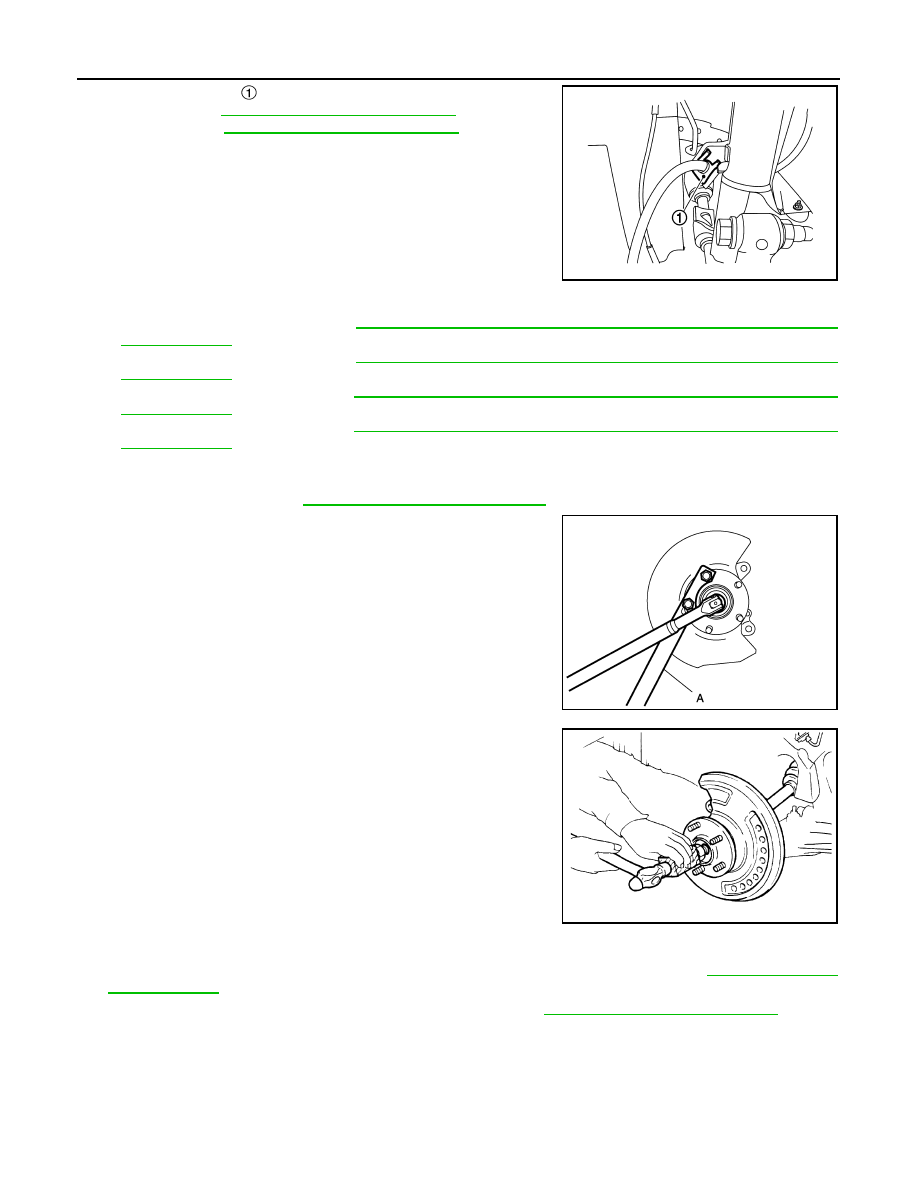
Remove lock plate
from strut assembly.
• LHD: Refer to
BR-24, "FRONT : Exploded View"
.
• RHD: Refer to
BR-88, "FRONT : Exploded View"
4.
Remove caliper assembly. Hang caliper assembly in a place where it will not interfere with work.
• LHD (1 PISTON TYPE): Refer to
BR-51, "BRAKE CALIPER ASSEMBLY (1 PISTON TYPE) : Removal
• LHD (2 PISTON TYPE): Refer to
BR-56, "BRAKE CALIPER ASSEMBLY (2 PISTON TYPE) : Removal
• RHD (1 PISTON TYPE): Refer to
BR-111, "BRAKE CALIPER ASSEMBLY (1 PISTON TYPE) : Removal
• RHD (2 PISTON TYPE): Refer to
BR-116, "BRAKE CALIPER ASSEMBLY (2 PISTON TYPE) : Removal
CAUTION:
Never depress brake pedal while brake caliper is removed.
5.
Remove disc rotor. Refer to
FAX-11, "Removal and Installation"
.
6.
Remove cotter pin, adjusting cap and then loosen wheel hub
lock nut, using a hub lock nut wrench (A) (SST: KV40104000).
7.
Patch wheel hub lock nut with a piece of wood. Hammer the
wood to disengage wheel hub and bearing assembly from drive
shaft.
NOTE:
Use suitable puller, if wheel hub and bearing assembly and drive
shaft cannot be separated even after performing the above pro-
cedure.
8.
Remove wheel hub lock nut.
9.
Remove transverse link from steering knuckle and front suspension member. Refer to
10. Separate steering outer socket from steering knuckle. Refer to
ST-22, "Removal and Installation"
JSDIA3795ZZ
JSDIA2708ZZ
JPDIG0070ZZ