содержание .. 1027 1028 1029 1030 ..
Nissan X-Trail 32. Manual - part 1029
PREPARATION
EM-13
< PREPARATION >
[MR20DD]
C
D
E
F
G
H
I
J
K
L
M
A
EM
N
P
O
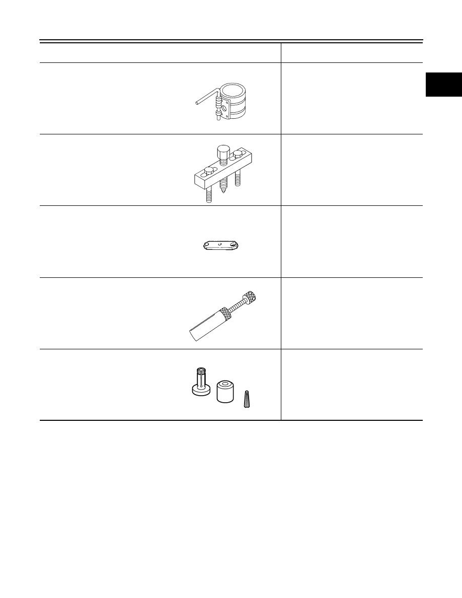
EM03470000
Piston ring compressor
Installing piston assembly into cylinder bore
KV11103000
Pulley puller
Removing crankshaft pulley
KV11105210
Stopper plate
Fixing drive plate and flywheel
KV10119600
Injector remover
Removing fuel injector
KV101197S0
Injector seal drift set
Installing fuel injector seal ring
Tool number
Tool name
Description
S-NT044
NT676
ZZA0009D
JPBIA3746ZZ
JPBIA3281ZZ