Nissan X-Trail 32. Manual - part 98


  Главная      Nissan     Nissan X-Trail 32 - Service Manual


поиск по сайту            


содержание   ..  96  97  98  99   ..


Nissan X-Trail 32. Manual - part 98


BCS-108

< BASIC INSPECTION >

CONFIGURATION (BCM)

: Items which confirm vehicle specifications

RAIN SENSOR CONFIG

WITH 

 WITHOUT

• WITH: With light & rain sensor
• WITHOUT: Without light & rain sensor

THEFT ALM AREA

WITHOUT 

 MODE4

• WITHOUT: Except for Europe (RHD) models
• MODE4: For Europe (RHD) models

HANDLE

LHD 

 RHD

ECM TYPE

MODE1 

 MODE2

• MODE1: For MR engine or QR engine models
• MODE2: Except for MR engine or QR engine models

DONGLE

WITH 

 WITHOUT

• WITH: For Europe (RHD) models
• WITHOUT: Except for Europe (RHD) models

TPMS

WITH 

 WITHOUT

HBA SYSTEM

WITH 

 WITHOUT

• WITH: With high beam assist system
• WITHOUT: Without high beam assist system

Key Fob Type

LCK/UNLCK

ALT TYPE

MODE1 

 MODE4

• MODE1: For MR engine or QR engine models
• MODE4: Except for MR engine or QR engine models

TRANSMISSION

MT with ABS 

 AT with ABS

• MT with ABS: M/T models
• AT with ABS: Except M/T models
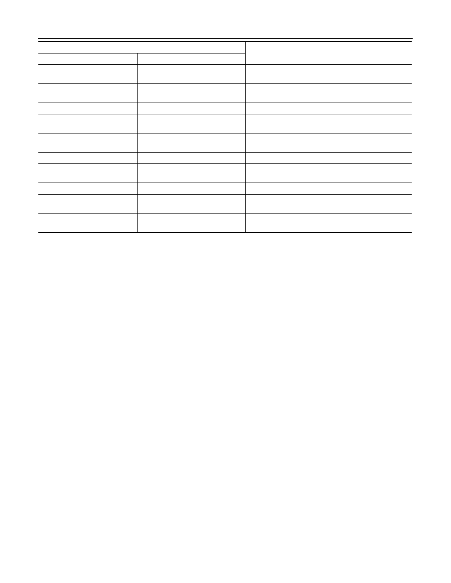
SETTING ITEM

NOTE

Items

Setting value

BCS

SHIPPING MODE CANCEL OPERATION

BCS-109

< BASIC INSPECTION >

C

D

E

F

G

H

I

J

K

L

B

A

O

P

N

SHIPPING MODE CANCEL OPERATION

Work Procedure

INFOID:0000000010688616

1.

SHIPPING MODE CANCEL OPERATION

1.

Turn ignition switch OFF.

2.

Push in (switch on) the extended storage fuse switch. Refer to 

PG-129, "How To Check"

.

3.

Turn ignition switch ON.

4.

Turn ignition switch OFF and wait at least 2 seconds.

>> GO TO 2.

2.

SHIPPING MODE CANCEL CHECK

1.

Turn ignition switch ON.

2.

Check that extended storage fuse warning message is not displayed on information display.

>> WORK END

BCS-110

< DTC/CIRCUIT DIAGNOSIS >

U1000 CAN COMM

DTC/CIRCUIT DIAGNOSIS

U1000 CAN COMM

DTC Description

INFOID:0000000010688617

DESCRIPTION

CAN (Controller Area Network) is a serial communication line for real time applications. It is an on-vehicle mul-
tiplex communication line with high data communication speed and excellent error detection ability. Modern
vehicle is equipped with many electronic control unit, and each control unit shares information and links with
other control units during operation (not independent). In CAN communication, control units are connected
with 2 communication lines (CAN H-line, CAN L-line) allowing a high rate of information transmission with less
wiring. Each control unit transmits/receives data but selectively reads required data only. CAN Communication
Signal Chart. Refer to 

LAN-41, "CAN COMMUNICATION SYSTEM : CAN Communication Signal Chart"

.

DTC DETECTION LOGIC

POSSIBLE CAUSE

CAN communication system

FAIL-SAFE

DTC CONFIRMATION PROCEDURE

1.

CHECK SELF-DIAG RESULT

 With CONSULT

1.

Turn ignition switch ON and wait for 2 seconds or more.

2.

Perform “Self Diagnostic Result” mode of “BCM” using CONSULT.

Is malfunctioning part detected?

YES

>> Refer to 

BCS-110, "Diagnosis Procedure"

.

NO-1

>> To check malfunction symptom before repair: Refer to 

GI-44, "Intermittent Incident"

.

NO-2

>> Confirmation after repair: INSPECTION END

Diagnosis Procedure

INFOID:0000000010688618

1.

CHECK CAN COMMUNICATION

Check CAN communication. Refer to 

LAN-17, "Trouble Diagnosis Flow Chart"

.

Is DTC “U1000–00” displayed?

YES

>> Repair or replace the malfunctioning part.

NO

>> Check intermittent incident. Refer to 

GI-44, "Intermittent Incident"

.

DTC

CONSULT display description

DTC Detection Condition

U1000–00

CAN COMM
(CAN communication circuit)

When BCM cannot communicate CAN communication signal continuously 
for 2 seconds or more.

BCS

U1010 CONTROL UNIT (CAN)

BCS-111

< DTC/CIRCUIT DIAGNOSIS >

C

D

E

F

G

H

I

J

K

L

B

A

O

P

N

U1010 CONTROL UNIT (CAN)

DTC Description

INFOID:0000000010688619

DTC DETECTION LOGIC

POSSIBLE CAUSE

BCM

FAIL-SAFE

DTC CONFIRMATION PROCEDURE

1.

CHECK SELF-DIAG RESULT

 With CONSULT

1.

Turn ignition switch ON.

2.

Perform “Self Diagnostic Result” mode of “BCM” using CONSULT.

Is malfunctioning part detected?

YES

>> Refer to 

BCS-111, "Diagnosis Procedure"

.

NO-1

>> To check malfunction symptom before repair: Refer to 

GI-44, "Intermittent Incident"

.

NO-2

>> Confirmation after repair: INSPECTION END

Diagnosis Procedure

INFOID:0000000010688620

1.

REPLACE BCM

When DTC “U1010–00” is detected, replace BCM.

>> Replace BCM. Refer to 

BCS-121, "Removal and Installation"

.

DTC

CONSULT display description

DTC Detection Condition

U1010–00

CONTROL UNIT (CAN)
[Control unit (CAN)]

BCM detected internal CAN communication circuit malfunction.


содержание   ..  96  97  98  99   ..