содержание .. 84 85 86 87 ..
Nissan X-Trail 32. Manual - part 86
BCS-60
< ECU DIAGNOSIS INFORMATION >
BCM
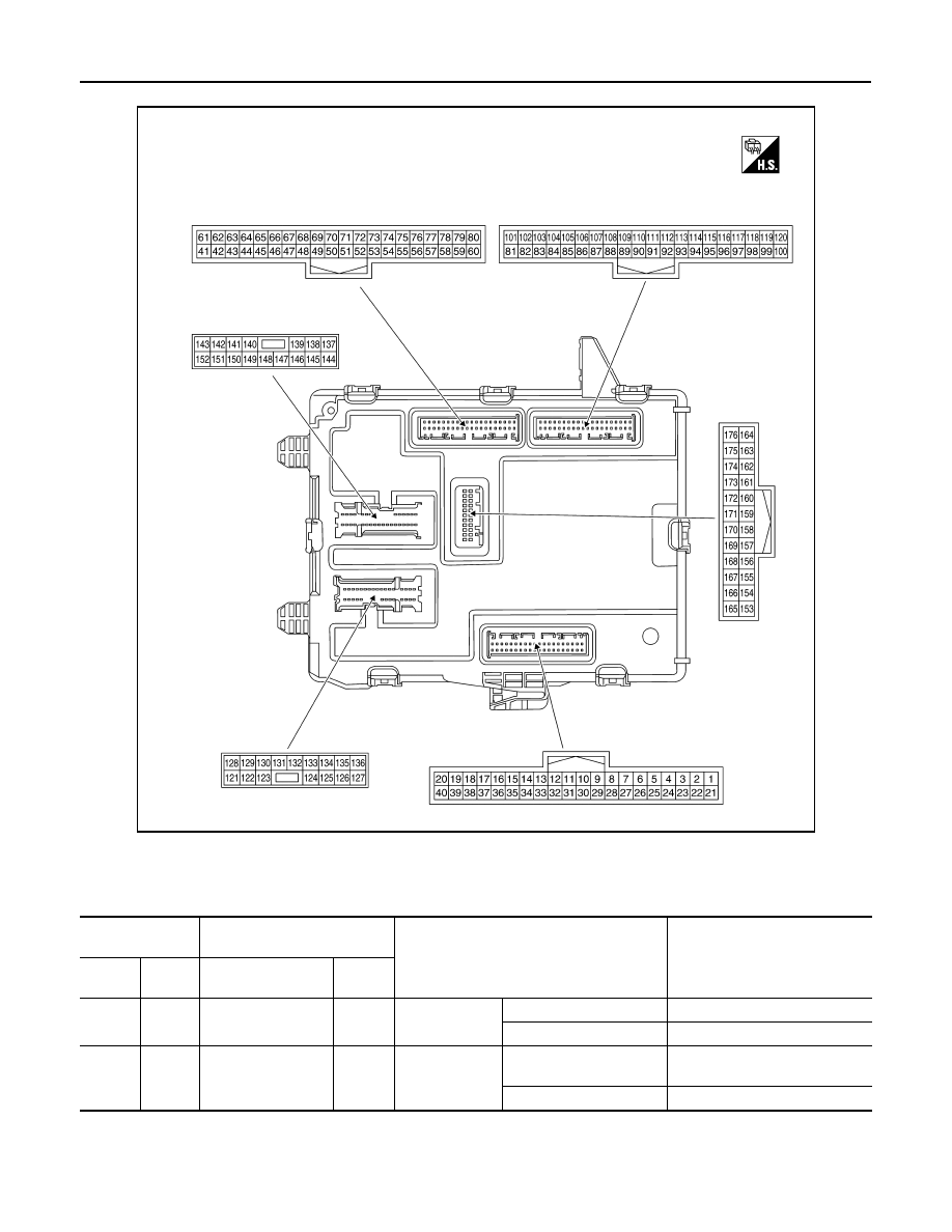
TERMINAL LAYOUT
PHYSICAL VALUES
NOTE:
Waveform reference
JMMIA1641ZZ
Terminal No.
(Wire color)
Description
Condition
Value
(Approx.)
+
−
Signal name
Input/
Output
6*
2
(R)
Ground
Back door opener
request switch
Input
Back door re-
quest switch
ON (Pressed)
0 – 0.5 V
OFF (Not pressed)
9 – 16 V
9*
1
(G)
Ground
Hands free sensor
Input
Hands free sen-
sor
Hold up hands to detec-
tion area
0 – 0.5 V
Other than above
9 – 16 V