содержание .. 28 29 30 31 ..
Nissan X-Trail 32. Manual - part 30
AV-112
< ECU DIAGNOSIS INFORMATION >
[WITH NAVIGATION]
AROUND VIEW MONITOR CONTROL UNIT
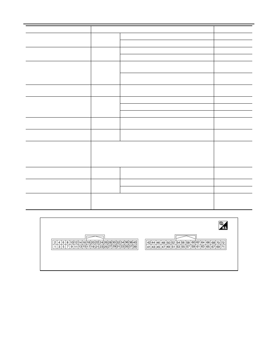
TERMINAL LAYOUT
PHYSICAL VALUES
Without BSW
PUMP COMM STATUS
Ignition switch
ON
When communication signal is input
OK
Other than the above
NG
ILL
Ignition switch
ON
When lighting switch is ON
ON
When lighting switch is OFF
OFF
ITS SW 1
Ignition switch
ON
Warning systems switch is ON. (Warning systems ON
indicator illuminates.)
ON
Warning systems switch is OFF. (Warning systems
ON indicator OFF.)
OFF
ITS SW 1 IND
Ignition switch
ON
—
OFF
TURN SIGNAL
Ignition switch
ON
Turn signal RH: ON
RIGHT
Turn signal LH: ON
LEFT
Turn signal: OFF
OFF
ITS SW 2
Ignition switch
ON
—
NO SET
ITS SW 2 IND
Ignition switch
ON
—
NO SET
VEHICLE SPEED
Ignition switch ON
Displays approxi-
mately the same
speed as the value
indicated on the
speedometer.
IDLE STOP STATUS
Ignition switch
ON
—
OFF
TRAILER HITCH SW
Ignition switch
ON
When a towing vehicle is connected
ON
Other than the above
OFF
STEERING ANGLE
Ignition switch ON
Displays a value
that corresponds to
the steering angle.
Monitor Item
Condition
Value/Status
JSNIA4749ZZ