Nissan Primera P12. Manual - part 680


  Главная      Nissan     Nissan Primera P12 - Service Manual


поиск по сайту            


содержание   ..  678  679  680  681   ..


Nissan Primera P12. Manual - part 680


PS-6

[F9Q]

STEERING WHEEL

STEERING WHEEL

PFP:48430

On-Vehicle Inspection and Service

EGS000NA

PLAY INSPECTION

1.

Turn steering wheel to straight-ahead position. Start engine and lightly turn steering wheel clockwise and
counterclockwise until front wheels start moving. Measure travel to starting point on circumference of
steering wheel.

2.

If play is outside specifications, check following parts for proper installation: steering gear assembly, front
suspension, axles, and steering column.

Check steering wheel for vertical, horizontal, or axial play.

Lift vehicle and check steering gear mounting bolts and nuts for looseness.

NEUTRAL POSITION INSPECTION

After the wheel alignment inspection, carry out the neutral position inspection. Refer to

FSU-6, "Wheel

Alignment"

.

Before removing steering wheel, check steering gear neutral position.

1.

Set vehicle to straight-ahead position, and check that steering wheel is in neutral position.

2.

If it is not in neutral position, remove steering wheel, and install again in properly.

3.

If it is not adjusted within two teeth from center of gear, loosen tie rod lock nut. Then turn it to opposite
direction to adjust until amount of left and right becomes equal.

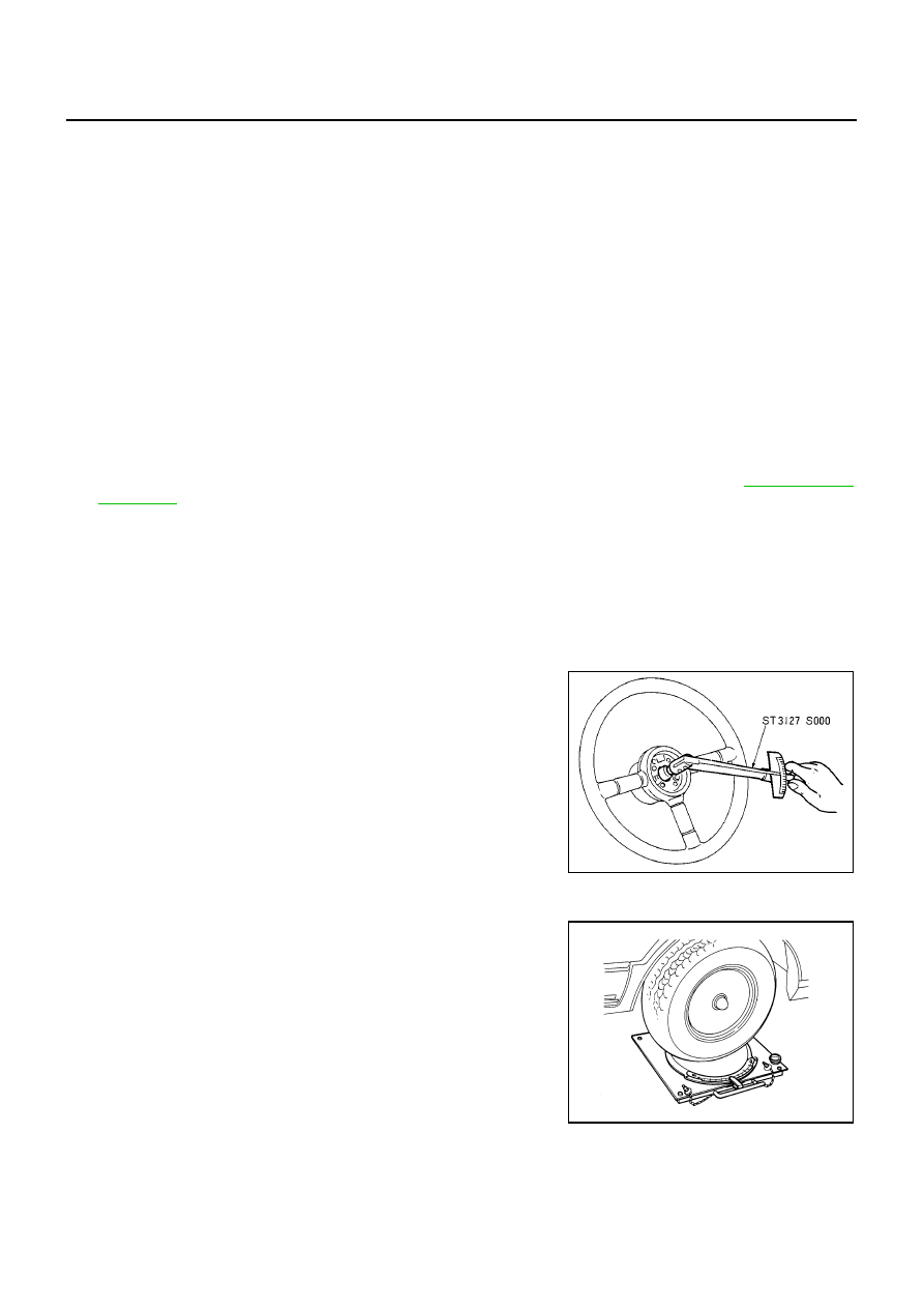
STEERING TORQUE CHECK

1.

Stop vehicle on a dry flat paved road and apply parking brake.

2.

Start engine and wait until power steering fluid warms up. Using
a preload gauge, check rotational torque of steering wheel.

3.

If torque is outside specifications, check rack sliding torque and
oil pump relief pressure.

STEERING ANGLE INSPECTION

After toe-in inspection, check steering angle. Place front wheels
on turning radius gauges and rear wheels on stands. Level the
vehicle. Check maximum inner and outer wheel steering angles
for LH and RH road wheels.

Steering wheel play inspection standard

: 0 - 35 mm (0 - 1.38 in)

Steering wheel axial end play

: 0 mm (0 in)

Tightening torque

: 145 - 185 N·m (15 - 18 kg·m, 107 - 136 ft·lb)

Steering torque

: 706 N·cm (72 kg·cm) or less

Rack sliding torque

: 145 - 255 N (14.8 - 26.0 kg,
32.6 - 57.3 lb)

Oil pump relief
hydraulic pressure

: To be informed

STA0005D

FAA0016D

STEERING WHEEL

PS-7

[F9Q]

C

D

E

F

H

I

J

K

L

M

A

B

PS

Start engine. With engine at idle, turn steering wheel from stop
to stop and measure steering angles.

If angles are outside specification, measure rack stroke.

If rack stroke is outside of specification, disassemble steering
gear to check rack stroke.

Steering angles are not adjustable. If any of steering angles is different from specified value, check steer-
ing gear, the column and the front suspension components for wear or damage. If any abnormality exists,
replace the malfunctioning parts.

Removal and Installation

EGS000NB

REMOVAL

1.

Remove air bag module. Refer to SRS section in P12 ECM (SM2E00-1P12E0E).

2.

Remove horn connector.

3.

Remove steering wheel mounting nut and paint mating marks on steering wheel body and top of column
shaft.

4.

Using a steering wheel puller, remove steering wheel.

INSTALLATION

Paying attention to following items, install in the reverse order of removal.

NOTE:

When reconnecting spiral cable, fix cable with a tape so that fixing case and rotating part keep aligned.
This will omit neutral position alignment procedure during spiral cable installation.

Neutral position (refer to figure)... Gently turn spiral cable clock-
wise until it comes to the stop. Then turn it counterclockwise
(approximately 3.0 turns) until centering mark is aligned with
adjustment mark. (Service part is fixed in neutral position with
stopper. It can be installed onto steering wheel without align-
ment once stopper is removed.)

CAUTION:

Place steering wheel as follows: Front wheels in straight-
ahead position. R mark on the cancel claw faces down. 3
bosses align with 3 holes behind steering wheel assembly.
Check that spiral cable is placed in neutral position and that
locating pin on the left of the spiral cable is aligned with the
locating pinhole behind the steering wheel assembly.

Do not rotate spiral cable more than necessary. Do not tighten them excessively. (The cable may
be torn off.)

After installation, check system for proper operation by observing air bag warning lamp.

If air bag indicator indicates any abnormal condition, use self-diagnosis function or CONSULT-II to
reset or cancel memory.

Inner wheel

: 37.5

°

+1

°

3

°

Outer wheel

: 30.5

°

Rack stroke

: 68 mm (2.68 in)

SGIA0055E

SGIA0080E

SGIA0096E

PS-8

[F9Q]

STEERING WHEEL

If air bag warning lamp still shows abnormal condition even after operation above, diagnose sys-
tem. Repair malfunctioning parts.

STEERING COLUMN

PS-9

[F9Q]

C

D

E

F

H

I

J

K

L

M

A

B

PS

STEERING COLUMN

PFP:48810

Removal and Installation

EGS000NC

CAUTION:

Care must be taken not to give axial impact to steering column assembly during removal and installa-
tion.

REMOVAL OF LOWER JOINT AND HOLE COVER

1.

Raise vehicle with front wheels in straight-ahead position.

2.

Mark lower joint and steering gear assembly with paint for easy installation. Remove pinch bolt from lower
side of lower joint.

3.

Remove mounting bolt and nut from upper side of lower joint.

4.

Remove footrest.

5.

Remove hole cover and lower joint from vehicle.

6.

Remove clamp and lower seal cover from hole cover.

INSTALLATION OF LOWER JOINT AND HOLE COVER

Refer to component diagram for tightening torque. Install in the reverse order of removal.

Connect lower joint onto steering gear assembly with slot on lower portion of lower joint engaged with
guide tip projection. Check guide tip is positioned as shown in the figure.

REMOVAL OF STEERING COLUMN ASSEMBLY

1.

Remove steering wheel and column cover. Refer to

PS-7, "Removal and Installation"

.

2.

Remove the instrument of the driver-side lower panel.

3.

Remove spiral cable. Refer to SRS section in P12 ESM (SM2E00-1P12E0E).

4.

Remove lower cover and mounting bolts and nuts on upper portion of lower joint.

MGIA0001E

1.

Steering column assembly

2.

Hole cover

3.

Lower joint

4.

Steering wheel

5.

Air bag module

6.

Spiral cable

7.

Column cover


содержание   ..  678  679  680  681   ..