содержание .. 508 509 510 511 ..
Nissan Primera P12. Manual - part 510
GW-36
REAR WINDOW DEFOGGER
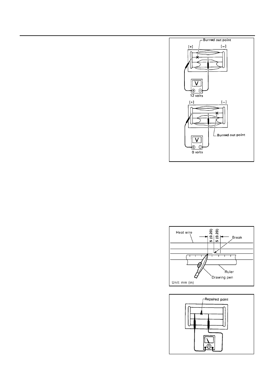
3.
If a filament is burned out, circuit tester registers 0 or battery
voltage.
4.
To locate burned out point, move probe to left and right along fil-
ament. Test needle will swing abruptly when probe passes the
point.
FILAMENT REPAIR
Repair Equipment
●
Conductive silver composition (Dupont NO. 4817 or equivalent)
●
Ruler 30 cm (11.8 in) long
●
Drawing pen
●
Heat gun
●
Alcohol
●
Cloth
Repairing Procedure
1.
Wipe broken heat wire and its surrounding area clean with a
cloth dampened alcohol.
2.
Apply a small amount of conductive silver composition to tip of
drawing pen.
Shake silver composition container before use.
3.
Place ruler on glass along broken line. Deposit conductive silver
composition on break with drawing pen. Slightly overlap existing
heat wire on both sides [preferably 5 mm (0.20 in)] of the break.
4.
After repair has been completed, check repaired wire for conti-
nuity. This check should be conducted 10 minutes after silver
composition is deposited.
Do not touch repaired area while test is being conducted.
SEL265
PIIA0215E
SEL012D