содержание .. 492 493 494 495 ..
Nissan Primera P12. Manual - part 494
GI-24
SERVICE INFORMATION FOR ELECTRICAL INCIDENT
SERVICE INFORMATION FOR ELECTRICAL INCIDENT
PFP:00000
How to Perform Efficient Diagnosis for an Electrical Incident
EAS000V0
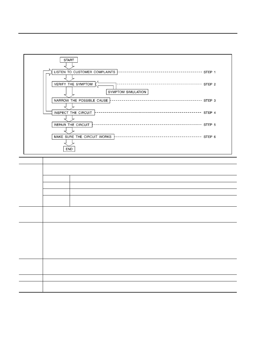
WORK FLOW
INCIDENT SIMULATION TESTS
Introduction
Sometimes the symptom is not present when the vehicle is brought in for service. If possible, re-create the
conditions present at the time of the incident. Doing so may help avoid a No Trouble Found Diagnosis. The fol-
lowing section illustrates ways to simulate the conditions/environment under which the owner experiences an
electrical incident.
The section is broken into the six following topics:
●
Vehicle vibration
SGI838
STEP
DESCRIPTION
STEP 1
Get detailed information about the conditions and the environment when the incident occurred.
The following are key pieces of information required to make a good analysis:
WHAT
Vehicle Model, Engine, Transmission/Transaxle and the System (i.e. Radio).
WHEN
Date, Time of Day, Weather Conditions, Frequency.
WHERE
Road Conditions, Altitude and Traffic Situation.
HOW
System Symptoms, Operating Conditions (Other Components Interaction).
Service History and if any After Market Accessories have been installed.
STEP 2
Operate the system, road test if necessary.
Verify the parameter of the incident.
If the problem cannot be duplicated, refer to “Incident Simulation Tests”.
STEP 3
Get the proper diagnosis materials together including:
●
Power Supply Routing
●
System Operation Descriptions
●
Applicable Service Manual Sections
●
Check for any Service Bulletins
Identify where to begin diagnosis based upon your knowledge of the system operation and the customer comments.
STEP 4
Inspect the system for mechanical binding, loose connectors or wiring damage.
Determine which circuits and components are involved and diagnose using the Power Supply Routing and Harness
Layouts.
STEP 5
Repair or replace the incident circuit or component.
STEP 6
Operate the system in all modes. Verify the system works properly under all conditions. Make sure you have not inad-
vertently created a new incident during your diagnosis or repair steps.