Nissan Primera P12. Manual - part 358


  Главная      Nissan     Nissan Primera P12 - Service Manual


поиск по сайту            


содержание   ..  356  357  358  359   ..


Nissan Primera P12. Manual - part 358


GLOW CONTROL SYSTEM

EC-617

[YD (WITHOUT EURO-OBD)]

C

D

E

F

G

H

I

J

K

L

M

A

EC

7.

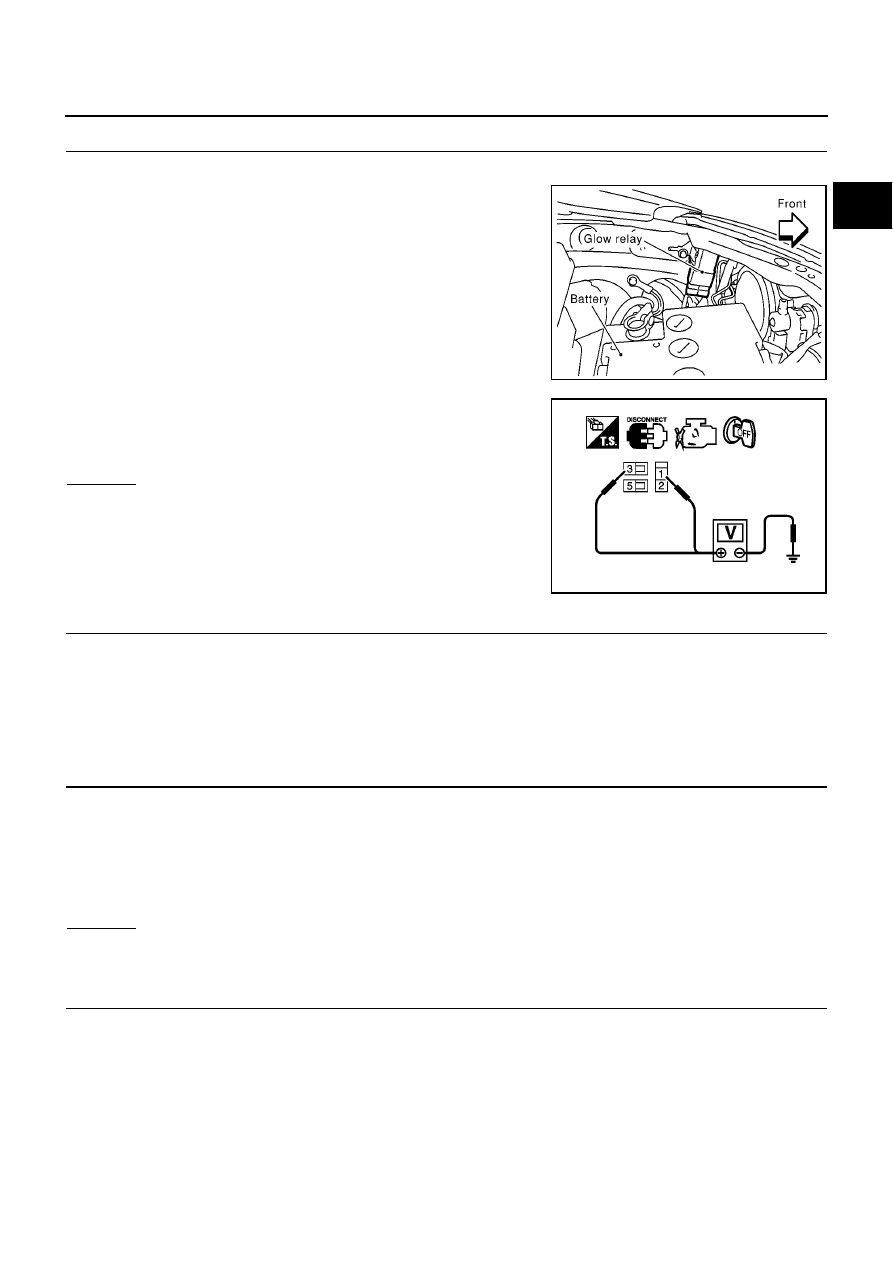
CHECK GLOW RELAY POWER SUPPLY CIRCUIT

1.

Turn ignition switch OFF.

2.

Disconnect glow relay.

3.

Check voltage between glow relay terminals 1, 3 and ground
with CONSULT-II or tester.

OK or NG

OK

>> GO TO 9.

NG

>> GO TO 8.

8.

DETECT MALFUNCTIONING PART

Check the following.

80A fusible link

Harness for open or short between glow relay and battery

>> Repair harness or connectors.

9.

CHECK GLOW RELAY OUTPUT SIGNAL CIRCUIT FOR OPEN AND SHORT

1.

Disconnect ECM harness connector.

2.

Check harness continuity between ECM terminal 37 and glow relay terminal 2.
Refer to Wiring Diagram.

3.

Also check harness for short to ground and short to power.

OK or NG

OK

>> GO TO 11.

NG

>> GO TO 10.

10.

DETECT MALFUNCTIONING PART

Check the following.

Harness connectors E62, F12

Harness for open or short between glow relay and ECM

>> Repair open circuit or short to ground or short to power in harness or connectors.

MBIB0078E

Voltage: Battery voltage

PBIB1413E

Continuity should exist.

EC-618

[YD (WITHOUT EURO-OBD)]

GLOW CONTROL SYSTEM

11.

CHECK HARNESS CONTINUITY BETWEEN GLOW RELAY AND GLOW PLUG FOR OPEN AND

SHORT

1.

Disconnect glow plug harness connector.

2.

Check harness continuity between glow relay terminal 5 and glow plug harness connector.
Refer to Wiring Diagram.

3.

Also check harness for short to ground and short to power.

OK or NG

OK

>> GO TO 12.

NG

>> Repair open circuit or short to ground or short to power in harness or connectors.

12.

CHECK GLOW RELAY

Refer to

EC-619, "Component Inspection"

.

OK or NG

OK

>> GO TO 13.

NG

>> Replace glow relay.

13.

CHECK GLOW PLUG

Refer to

EC-619, "Component Inspection"

.

OK or NG

OK

>> GO TO 14.

NG

>> Replace glow plug.

14.

CHECK INTERMITTENT INCIDENT

Refer to

EC-408, "TROUBLE DIAGNOSIS FOR INTERMITTENT INCIDENT"

.

>> INSPECTION END

Continuity should exist.

GLOW CONTROL SYSTEM

EC-619

[YD (WITHOUT EURO-OBD)]

C

D

E

F

G

H

I

J

K

L

M

A

EC

Component Inspection

EBS015CH

GLOW RELAY

Check continuity between glow relay terminals 3 and 5 under the fol-
lowing conditions.

Operation takes less than 1 second.

GLOW PLUG

1.

Remove glow plug connecting plate.

2.

Check glow plug resistance.

NOTE:

Do not bump glow plug heating element. If it is bumped,
replace glow plug with a new one.

If glow plug is dropped from a height of 10 cm (3.94 in) or
higher, replace with a new one.

If glow plug installation hole is contaminated with car-
bon, remove it with a reamer or suitable tool.

Hand-tighten glow plug by turning it two or three times,
then tighten using a tool to specified torque.

Removal and Installation

EBS015CI

GLOW PLUG

Refer to

EM-34, "GLOW PLUG"

.

Conditions

Continuity

12V direct current supply between ter-
minals 1 and 2

Yes

No current supply

No

PBIB0428E

Resistance: Approximately 0.8

[at 25

°

C (77

°

F)]

: 20.1 N-m (2.1 kg-m, 15 ft-lb)

PBIB0429E

EC-620

[YD (WITHOUT EURO-OBD)]

EGR VOLUME CONTROL SYSTEM

EGR VOLUME CONTROL SYSTEM

PFP:14710

Description

EBS015CJ

SYSTEM DESCRIPTION

*: This signal is sent to the ECM through CAN communication line.

This system controls flow rate of EGR led from exhaust manifold to intake manifold. The opening of the EGR
by-pass passage in the EGR volume control valve changes to control the flow rate. A built-in step motor
moves the valve in steps corresponding to the ECM output pulses. The opening of the valve varies for opti-
mum engine control. The optimum value stored in the ECM is determined by considering various engine con-
ditions.
The EGR volume control valve remains close under the following conditions.

Engine stopped

Engine starting

Low engine coolant temperature

Excessively high engine coolant temperature

High engine speed

Wide open throttle

COMPONENT DESCRIPTION
EGR Volume Control Valve

The EGR volume control valve uses a step motor to control the flow
rate of EGR from exhaust manifold. This motor has four winding
phases. It operates according to the output pulse signal of the ECM.
Two windings are turned ON and OFF in sequence. Each time an
ON pulse is issued, the valve opens or closes, changing the flow
rate. When no change in the flow rate is needed, the ECM does not
issue the pulse signal. A certain voltage signal is issued so that the
valve remains at that particular opening.

CONSULT-II Reference Value in Data Monitor Mode

EBS015CK

Specification data are reference values.

Sensor

Input Signal to ECM

ECM Function

Actuator

Crankshaft position sensor

Engine speed

EGR volume con-
trol

EGR volume control
valve

Vehicle speed sensor*

Vehicle speed

Engine coolant temperature sensor

Engine coolant temperature

Ignition switch

Start signal

Accelerator pedal position sensor

Accelerator pedal position

Mass air flow sensor

Amount of intake air

Air conditioner switch*

Air conditioner operation

SEF908Y

SEF411Y


содержание   ..  356  357  358  359   ..