содержание .. 350 351 352 353 ..
Nissan Primera P12. Manual - part 352
DTC P1275 FUEL PUMP
EC-593
[YD (WITHOUT EURO-OBD)]
C
D
E
F
G
H
I
J
K
L
M
A
EC
6.
CHECK INTERMITTENT INCIDENT
Refer to
EC-408, "TROUBLE DIAGNOSIS FOR INTERMITTENT INCIDENT"
.
>> INSPECTION END
Component Inspection
EBS015BJ
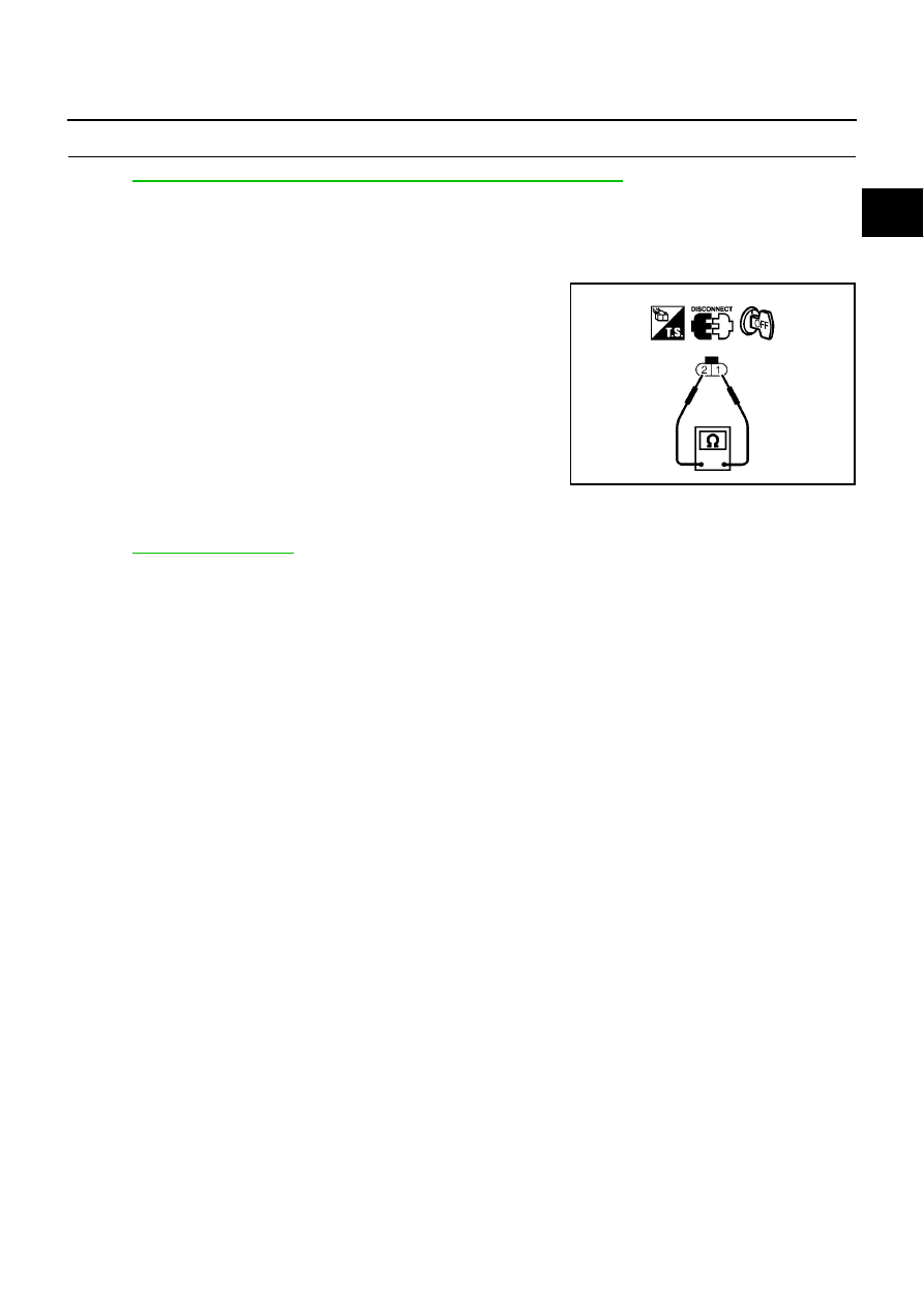
FUEL PUMP
1.
Check continuity between fuel pump terminals 1 and 2.
2.
If NG, replace fuel pump.
Removal and Installation
EBS015BK
FUEL PUMP
Refer to
.
Continuity should exist.
MBIB0623E