Nissan Primera P12. Manual - part 331


  Главная      Nissan     Nissan Primera P12 - Service Manual


поиск по сайту            


содержание   ..  329  330  331  332   ..


Nissan Primera P12. Manual - part 331


DTC P0340 CMP SENSOR

EC-509

[YD (WITHOUT EURO-OBD)]

C

D

E

F

G

H

I

J

K

L

M

A

EC

Diagnostic Procedure

EBS0157L

1.

CHECK STARTING SYSTEM

Turn ignition switch to START position.

Yes or No

Yes

>> GO TO 2.

No

>> Check starting system. (Refer to

SC-20, "STARTING SYSTEM"

.)

2.

CHECK GROUND CONNECTIONS

1.

Turn ignition switch OFF.

2.

Loosen and retighten engine ground screws. Refer to

EC-415,

"Ground Inspection"

.

OK or NG

OK

>> GO TO 3.

NG

>> Repair or replace ground connections.

3.

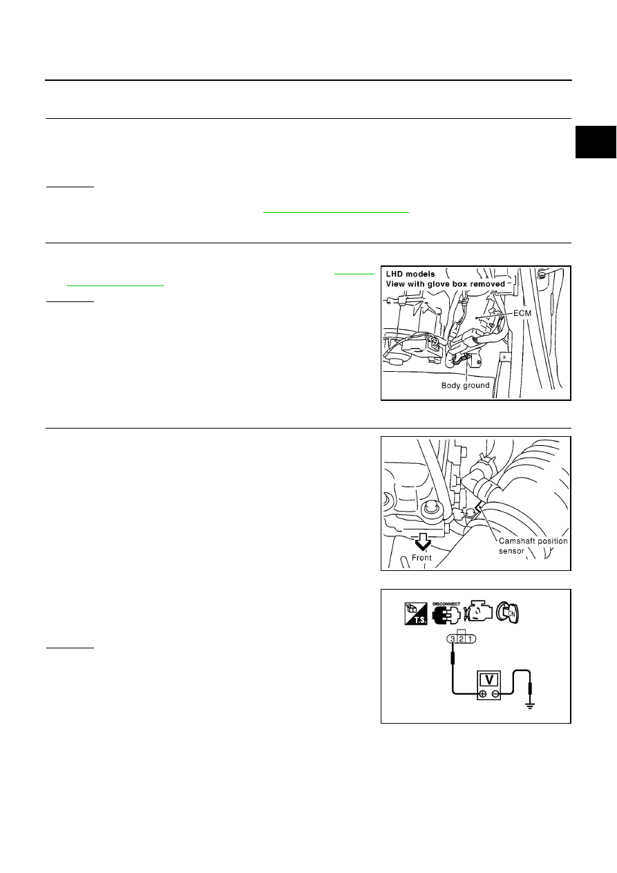
CHECK CMP SENSOR POWER SUPPLY CIRCUIT

1.

Disconnect camshaft position (CMP) sensor harness connector.

2.

Turn ignition switch ON.

3.

Check voltage between CMP sensor terminal 3 and ground with
CONSULT-II or tester.

OK or NG

OK

>> GO TO 4.

NG

>> Repair open circuit or short to ground or short to power

in harness or connectors.

Does the engine turn over?

Does the starter motor operate?

MBIB0915E

MBIB0076E

Voltage: Approximately 5.3V

MBIB1010E

EC-510

[YD (WITHOUT EURO-OBD)]

DTC P0340 CMP SENSOR

4.

CHECK CMP SENSOR GROUND CIRCUIT FOR OPEN AND SHORT

1.

Turn ignition switch OFF.

2.

Disconnect ECM harness connector.

3.

Check harness continuity between ECM terminal 66 and CMP sensor terminal 2.

4.

Also check harness for short to ground and short to power.

OK or NG

OK

>> GO TO 5.

NG

>> Repair open circuit or short to ground or short to power in harness or connectors.

5.

CHECK CMP SENSOR INPUT SIGNAL CIRCUIT FOR OPEN AND SHORT

1.

Check harness continuity between ECM terminal 47 and CMP sensor terminal 1.
Refer to Wiring Diagram.

2.

Also check harness for short to ground or short to power.

OK or NG

OK

>> GO TO 6.

NG

>> Repair open circuit or short to ground or short to power in harness or connectors.

6.

CHECK CAMSHAFT POSITION SENSOR

Refer to

EC-510, "Component Inspection"

.

OK or NG

OK

>> GO TO 7.

NG

>> Replace camshaft position sensor.

7.

CHECK INTERMITTENT INCIDENT

Refer to

EC-408, "TROUBLE DIAGNOSIS FOR INTERMITTENT INCIDENT"

.

>> INSPECTION END

Component Inspection

EBS0157M

CAMSHAFT POSITION SENSOR

1.

Loosen the fixing bolt of the sensor.

2.

Disconnect camshaft position sensor harness connector.

3.

Remove the sensor.

4.

Visually check the sensor for chipping.

Continuity should exist.

Continuity should exist.

MBIB0647E

DTC P0340 CMP SENSOR

EC-511

[YD (WITHOUT EURO-OBD)]

C

D

E

F

G

H

I

J

K

L

M

A

EC

5.

Check resistance as shown in the figure.

6.

If NG, replace camshaft position sensor.

Removal and Installation

EBS0157N

CAMSHAFT POSITION SENSOR

Refer to

EM-35, "VACUUM PUMP"

Terminal No. (Polarity)

Resistance

[at 25

°

C (77

°

F)]

1 (+) - 2 (-)

Except 0

1 (+) - 3 (-)

2 (+) - 3 (-)

Except 0 or

MBIB1009E

EC-512

[YD (WITHOUT EURO-OBD)]

DTC P0341 CMP SENSOR

DTC P0341 CMP SENSOR

PFP:23731

Description

EBS0157O

The camshaft position sensor identifies a particular cylinder by
means of signals from the sensing plate (with five protrusions)
installed to the camshaft. The datum signal output is detected 90

°

signal and sent to the ECM.

ECM Terminals and Reference Value

EBS0157P

Specification data are reference values and are measured between each terminal and ground.
Pulse signal is measured by CONSULT-II.

CAUTION:

Do not use ECM ground terminals when measuring input/output voltage. Doing so may result in dam-
age to the ECM's transistor. Use a ground other than ECM terminals, such as the ground.

: Average voltage for pulse signal (Actual pulse signal can be confirmed by oscilloscope.)

On Board Diagnosis Logic

EBS0157Q

MBIB0618E

TERMI-

NAL

NO.

WIRE

COLOR

ITEM

CONDITION

DATA

(DC Voltage and Pulse Signal)

45

R

Camshaft position sensor
power supply

[Ignition switch ON]

Approximately 5.3V

47

B

Camshaft position sensor

[Engine is running]

Warm-up condition

Idle speed

0 - 6V

[Engine is running]

Warm-up condition

Engine speed is 2,000 rpm

0 - 6V

66

W

Camshaft position sensor
ground

[Ignition switch ON]

Approximately 0.3V

67

Sensor ground
(Sensors shield circuit)

[Ignition switch ON]

Approximately 0.3V

MBIB0877E

MBIB0878E

DTC No.

Trouble diagnosis name

DTC detecting condition

Possible cause

P0341

Camshaft position sensor
circuit range/performance

Camshaft position sensor signal is not in the nor-
mal pattern when engine is running.

Harness connectors
(The sensor circuit is opener
shorted.)

Camshaft position sensor

Signal plate


содержание   ..  329  330  331  332   ..