содержание .. 234 235 236 237 ..
Nissan Primera P12. Manual - part 236
DTC P0122, P0123 APP SENSOR
EC-129
[YD (WITH EURO-OBD)]
C
D
E
F
G
H
I
J
K
L
M
A
EC
2.
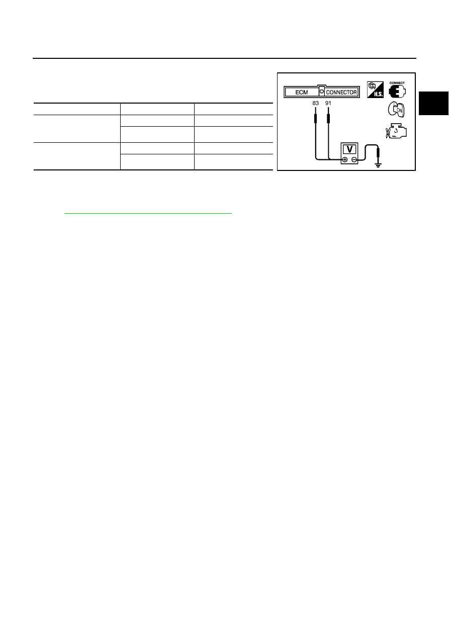
Turn ignition switch ON.
3.
Check voltage between ECM terminals 83 (APP sensor 1 sig-
nal), 91 (APP sensor 2 signal) and body ground under the fol-
lowing conditions.
4.
If NG, replace accelerator pedal assembly.
Removal and Installation
EBS013LY
ACCELERATOR PEDAL
Refer to
ACC-2, "ACCELERATOR CONTROL SYSTEM"
.
Terminal
Accelerator pedal
Voltage
83
(Accelerator pedal position
sensor 1)
Fully released
0.5 - 1.0V
Fully depressed
4.2 - 5.2V
91
(Accelerator pedal position
sensor 2)
Fully released
0.4 - 0.7V
Fully depressed
2.2 - 2.7V
MBIB0615E