Nissan Primera P12. Manual - part 210


  Главная      Nissan     Nissan Primera P12 - Service Manual


поиск по сайту            


содержание   ..  208  209  210  211   ..


Nissan Primera P12. Manual - part 210


ENGINE CONTROL SYSTEM

EC-25

[YD (WITH EURO-OBD)]

C

D

E

F

G

H

I

J

K

L

M

A

EC

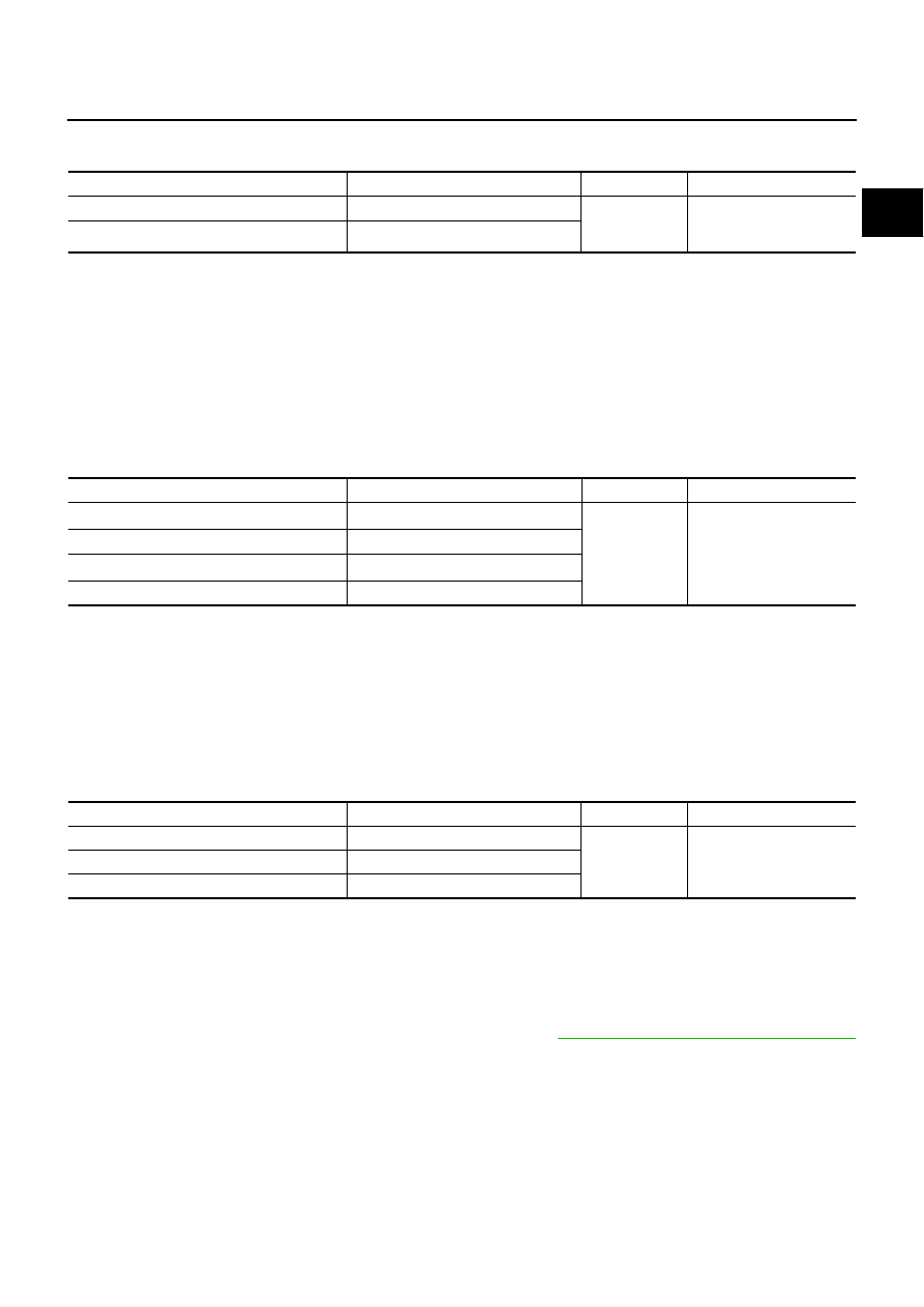
DECELERATION CONTROL
Input/Output Signal Chart

The ECM sends a fuel cut signal to the fuel injectors and fuel pump during deceleration for better fuel effi-
ciency. The ECM determines the time of deceleration according to signals from the accelerator pedal position
sensor and crankshaft position sensor.

Fuel Injection Timing Control System

EBS013J6

DESCRIPTION

The target fuel injection timing in accordance with the engine speed and the fuel injection amount are recorded
as a map in the ECM beforehand. The ECM determines the optimum injection timing using sensor signals
accordance with the map.

Air Conditioning Cut Control

EBS013J7

INPUT / OUTPUT SIGNAL CHART

*1: The input signal is sent to the ECM through CAN communication line.
*2: The output signal is sent from the ECM through CAN communication line.

SYSTEM DESCRIPTION

This system improves acceleration when the air conditioner is used.
When the accelerator pedal is fully depressed, the air conditioner is turned off for a few seconds.
When engine coolant temperature becomes excessively high, the air conditioner is turned off. This continues
until the engine coolant temperature returns to normal.

Fuel Cut Control (At No Load & High Engine Speed)

EBS013J8

INPUT/OUTPUT SIGNAL CHART

*: The input signal is sent to the ECM through CAN communication line.

If the engine speed is above 2,800 rpm under no load (for example, the shift position is neutral and engine
speed is over 2,800 rpm) fuel will be cut off after some time. The exact time when the fuel is cut off varies
based on engine speed. Fuel cut will be operated until the engine speed reaches 1,500 rpm, then fuel cut will
be cancelled.

NOTE:
This function is different from deceleration control listed under

EC-23, "Fuel Injection Control System"

.

Sensor

Input Signal to ECM

ECM Function

Actuator

Accelerator pedal position sensor

Accelerator pedal position

Fuel injection
control (Decel-
eration control)

Fuel injector
Fuel pump

Crankshaft position sensor

Engine speed

Sensor

Input Signal to ECM

ECM Function

Actuator

Air conditioner switch*

1

Air conditioner ON signal

Air conditioner
cut control

Air conditioner relay*

2

Accelerator pedal position sensor

Accelerator pedal opening angle

Vehicle speed sensor*

1

Vehicle speed

Engine coolant temperature sensor

Engine coolant temperature

Sensor

Input Signal to ECM

ECM Function

Actuator

Vehicle speed sensor*

Vehicle speed

Fuel cut control

Fuel injector

Accelerator pedal position sensor

Accelerator pedal position

Crankshaft position sensor

Engine speed

EC-26

[YD (WITH EURO-OBD)]

ENGINE CONTROL SYSTEM

Crankcase Ventilation System

EBS013J9

DESCRIPTION

In this system, blow-by gas is sucked into the air duct after oil separation by oil separator in the rocker cover.

INSPECTION
Ventilation Hose

1.

Check hoses and hose connections for leaks.

2.

Disconnect all hoses and clean with compressed air. If any hose
cannot be freed of obstructions, replace.

CAN Communication

EBS013JA

SYSTEM DESCRIPTION

CAN (Controller Area Network) is a serial communication line for real time application. It is an on-vehicle mul-
tiplex communication line with high data communication speed and excellent error detection ability. Many elec-
tronic control units are equipped onto a vehicle, and each control unit shares information and links with other
control units during operation (not independent). In CAN communication, control units are connected with 2
communication lines (CAN H line, CAN L line) allowing a high rate of information transmission with less wiring.
Each control unit transmits/receives data but selectively reads required data only.

PBIB0590E

SEC692

ENGINE CONTROL SYSTEM

EC-27

[YD (WITH EURO-OBD)]

C

D

E

F

G

H

I

J

K

L

M

A

EC

MODELS WITH ESP
System Diagram

LHD models

RHD models

Input/Output Signal Chart

T: Transmit R: Receive

SKIA1524E

SKIA1538E

Signals

ECM

ESP/ TCS /

ABS control

unit

Steering

angle sensor

Smart

entrance

control unit

Tyre pres-

sure monitor-

ing control

unit

Combination

meter

Engine speed signal

T

R

R

Accelerator pedal position signal

T

R

Steering angle sensor signal

R

T

Air conditioner switch signal

R

T

MI signal

T

R

Glow indicator lamp signal

T

R

Engine coolant temperature signal

T

R

Fuel consumption signal

T

R

Vehicle speed signal

T

R

R

R

T

Seat belt reminder signal

R

T

Lighting switch position signal

T

R

Flashing indicator signal

T

R

Engine cooling fan speed signal

T

R

Child lock indicator signal

T

R

Door switches state signal

T

R

A/C compressor signal

T

R

Tyre pressure signal

T

R

ASCD SET lamp signal

T

R

ASCD CRUISE lamp signal

T

R

EC-28

[YD (WITH EURO-OBD)]

ENGINE CONTROL SYSTEM

MODELS WITHOUT ESP
System Diagram

LHD models

RHD models

Input/Output Signal Chart

T: Transmit R: Receive

SKIA1525E

SKIA1539E

Signals

ECM

ABS actuator

and electric

unit (control

unit)

Smart entrance

control unit

Tyre pressure

monitoring

control unit

Combination

meter

Engine speed signal

T

R

Air conditioner switch signal

R

T

MI signal

T

R

Glow indicator lamp signal

T

R

Engine coolant temperature signal

T

R

Fuel consumption signal

T

R

Vehicle speed signal

T

R

R

R

T

Seat belt reminder signal

R

T

Lighting switch position signal

T

R

Flashing indicator signal

T

R

Engine cooling fan speed signal

T

R

Child lock indicator signal

T

R

Door switches state signal

T

R

A/C compressor signal

T

R

Tyre pressure signal

T

R

ASCD SET lamp signal

T

R

ASCD CRUISE lamp signal

T

R


содержание   ..  208  209  210  211   ..