содержание .. 29 30 31 32 ..
Nissan Primera P12. Manual - part 31
SUNLOAD SENSOR
ATC-117
C
D
E
F
G
H
I
K
L
M
A
B
ATC
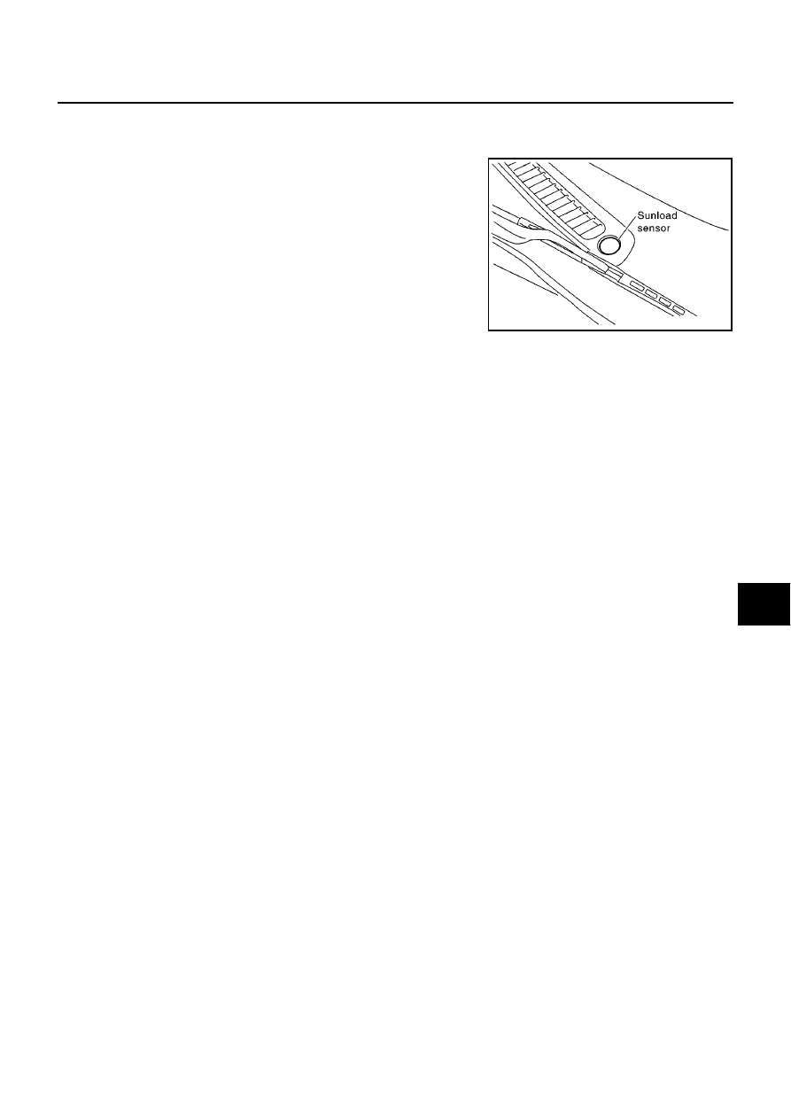
SUNLOAD SENSOR
PFP:27721
Removal and Installation
EJS002YI
1.
Remove the instrument panel.
2.
Remove the sunload sensor.
RJIA0165E
|
|
|
содержание .. 29 30 31 32 ..
SUNLOAD SENSOR ATC-117 C D E F G H I K L M A B ATC SUNLOAD SENSOR PFP:27721 Removal and Installation EJS002YI 1. Remove the instrument panel. 2. Remove the sunload sensor. RJIA0165E |