содержание .. 12 13 14 15 ..
Nissan Primera P12. Manual - part 14
TROUBLE DIAGNOSIS
ATC-49
C
D
E
F
G
H
I
K
L
M
A
B
ATC
FUNCTION CONFIRMATION PROCEDURE
1.
SET IN SELF-DIAGNOSTIC MODE
Method 1 (Without navigation system, or with navigation system)
1.
Turn ignition switch to ON.
2.
Within 10 seconds after starting engine (ignition switch is turned ON.), press and hold OFF switch for at
least 5 seconds.
3.
The self-diagnosis (step 1) should start.
Method 2 (Only with navigation system)
1.
Turn OFF the audio system.
2.
While pressing “Vehicle Information” switch, turn audio switch (volume adjustment dial) by at least 30
notches.
3.
Trouble diagnosis initial screen appears. Using joystick, select “Confirmation and Adjustment”. And press
“Confirm”.
4.
Confirmation and adjustment initial screen appears. Using joystick, select “Air-conditioner trouble diagno-
sis”, and press “Confirm” to start self-diagnosis (step 1).
CAUTION:
-If battery voltage drops below 12V during step diagnosis 3, actuator speed becomes slower and as a
result, the system may generate an error even when operation is normal. To avoid this, start engine
before performing this diagnosis.
>> GO TO 2.
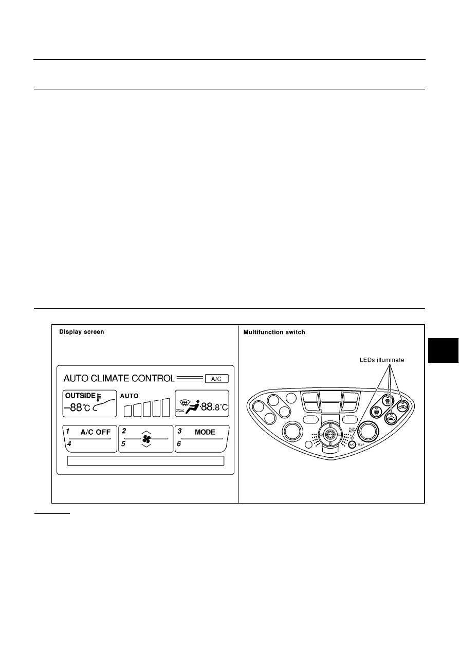
2.
STEP 1 - LEDS AND DISPLAY ARE CHECKED
Check LEDs illuminate and display screen.
OK or NG
OK
>> GO TO 3.
NG
>> Malfunctioning OFF switch or LEDs.
>> Check multi-function switch.
RJIA0753E