Nissan Primera P12. Manual - part 3


  Главная      Nissan     Nissan Primera P12 - Service Manual


поиск по сайту            


содержание   ..  1  2  3  4  ..


Nissan Primera P12. Manual - part 3


PRECAUTIONS

ATC-5

C

D

E

F

G

H

I

K

L

M

A

B

ATC

injury or property damage. Additional health and safety information may be obtained from refriger-
ant manufacturers.

Lubricant Precautions

EJS002X6

Use only specified lubricant for the HFC-134a (R-134a) A/C system and HFC-134a (R-134a) components.
If lubricant other than that specified is used, compressor malfunction is likely to occur.

The specified HFC-134a (R-134a) lubricant rapidly absorbs moisture from the atmosphere. The following
handling precautions must be observed:

When removing refrigerant components from a vehicle, immediately cap (seal) the component to minimize
the entry of moisture from the atmosphere.

When installing refrigerant components to a vehicle, do not remove the caps (unseal) until just before con-
necting the components. Connect all refrigerant loop components as quickly as possible to minimize the
entry of moisture into system.

Only use the specified lubricant from a sealed container. Immediately reseal containers of lubricant. With-
out proper sealing, lubricant will become moisture saturated and should not be used.

Avoid breathing A/C refrigerant and lubricant vapor or mist. Exposure may irritate eyes, nose and throat.
Use only approved recovery/recycling eequipment to discharge HFC-134a (R-134a) refrigerant. If acci-
dental system discharge occurs, ventilate work area before resuming service. Additional health and safety
information may be obtained from refrigerant and lubricant manufacturers.

Do not allow lubricant (Nissan A/C System Oil Type S) to come in contact with styrofoam parts. Damage
may result.

Precautions for Refrigerant Connection

EJS003A1

A new type refrigerant connection has been introduced to all refrigerant lines except the following location.

Expansion valve to cooling unit

Refrigerant pressure sensor or dual-pressure switch

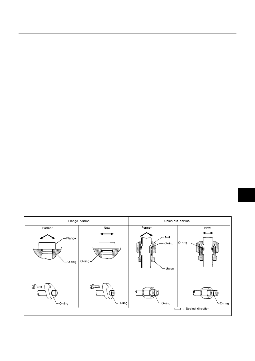
FEATURES OF NEW TYPE REFRIGERANT CONNECTION

The O-ring has been relocated. It has also been provided with a groove for proper installation. This elimi-
nates the chance of the O-ring being caught in, or damaged by, the mating part. The sealing direction of
the O-ring is now set vertically in relation to the contacting surface of the mating part to improve sealing
characteristics.

The reaction force of the O-ring will not occur in the direction that causes the joint to pull out, thereby facil-
itating piping connections.

SHA815E

ATC-6

PRECAUTIONS

O-RING AND REFRIGERANT CONNECTION
F9Q Engine Models

CAUTION:

The new and former refrigerant connections use different O-ring configurations. Do not confuse O-
rings since they are not interchangeable. If a wrong O-ring is installed, refrigerant will leak at, or
around, the connection.

O-Ring Part Numbers and Specifications

RJIA2359E

Connection

type

Piping connection point

Part number

Qty.

Remarks

New

Low-pressure flexible hose to heater & cooling unit

92473 N8210

1

O-ring size: 16mm

High-pressure pipe to heater & cooling unit

92471 N8210

1

O-ring size: 8mm

Condenser to high-pressure flexible hose

92472 N8210

1

O-ring size: 12mm

Condenser to high-pressure pipe

92471 N8210

1

O-ring size: 8mm

Compressor to low-pressure flexible hose

92474 N8210

1

O-ring size: 19mm
(Except F9Q engine)

7703065315

2

Renault part (F9Q engine)

Compressor to high-pressure flexible hose

92472 N8210

1

O-ring size: 12mm
(Except F9Q engine)

7703065316

2

Renault part (F9Q engine)

Liquid tank to condenser pipe

Inlet

92471 N8210

1

O-ring size: 8mm

Outlet

Former

Refrigerant pressure sensor or dual-pressure switch

J2476 89956

1

O-ring size: 10mm

Expansion valve to evaporator

Inlet

92475 71L00

1

O-ring size: 12mm

Outlet

92475 72L00

1

O-ring size: 16mm

PRECAUTIONS

ATC-7

C

D

E

F

G

H

I

K

L

M

A

B

ATC

WARNING:

Make sure all refrigerant is discharged into the recycling equipment and the pressure in the system is
less than atmospheric pressure. Then gradually loosen the discharge side hose fitting and remove it.

CAUTION:

When replacing or cleaning refrigerant cycle components, observe the following.

When the compressor is removed, store it in the same position as it is when mounted on the car.
Malfunction to do so will cause lubricant to enter the low pressure chamber.

When connecting tubes, always use a torque wrench and a back-up wrench.

After disconnecting tubes, immediately plug all openings to prevent entry of dirt and moisture.

When installing an air conditioner in the vehicle, connect the pipes as the final stage of the opera-
tion. Do not remove the seal caps of pipes and other components until just before required for
connection.

Allow components stored in cool areas to warm to working area temperature before removing seal
caps. This prevents condensation from forming inside A/C components.

Thoroughly remove moisture from the refrigeration system before charging the refrigerant.

Always replace used O-rings.

When connecting tube, apply lubricant to circle of the O-rings shown in illustration. Be careful not
to apply lubricant to threaded portion.
Lubricant name: Nissan A/C System Oil Type S
Part number: KLH00-PAGS0

O-ring must be closely attached to dented portion of tube.

When replacing the O-ring, be careful not to damage O-ring and tube.

Connect tube until you hear it click, then tighten the nut or bolt by hand until snug. Make sure that
the O-ring is installed to tube correctly.

After connecting line, conduct leak test and make sure that there is no leakage from connections.
When the gas leaking point is found, disconnect that line and replace the O-ring. Then tighten con-
nections of seal seat to the specified torque.

Precautions for Servicing Compressor

EJS002X8

Plug all openings to prevent moisture and foreign matter from entering.

When the compressor is removed, store it in the same position as it is when mounted on the car.

When replacing or repairing compressor, follow “Maintenance of Lubricant Quantity in Compres-
sor” exactly. Refer to

ATC-21, "Maintenance of Lubricant Quantity in Compressor"

.

Keep friction surfaces between clutch and pulley clean. If the surface is contaminated, with lubri-
cant, wipe it off by using a clean waste cloth moistened with thinner.

RHA861F

ATC-8

PRECAUTIONS

After compressor service operation, turn the compressor shaft by hand more than five turns in
both directions. This will equally distribute lubricant inside the compressor. After the compressor
is installed, let the engine idle and operate the compressor for one hour.

After replacing the compressor magnet clutch, apply voltage to the new one and check for usual
operation.

Precautions for Service Equipment

EJS002X9

RECOVERY/RECYCLING EQUIPMENT

Be certain to follow the manufacturers instructions for machine operation and machine maintenance. Never
introduce any refrigerant other than that specified into the machine.

ELECTRONIC LEAK DETECTOR

Be certain to follow the manufacturer's instructions for tester operation and tester maintenance.

VACUUM PUMP

The lubricant contained inside the vacuum pump is not compatible
with the specified lubricant for HFC-134a (R-134a) A/C systems.
The vent side of the vacuum pump is exposed to atmospheric pres-
sure. So the vacuum pump lubricant may migrate out of the pump
into the service hose. This is possible when the pump is switched off
after evacuation (vacuuming) and hose is connected to it.
To prevent this migration, use a manual valve placed near the hose-
to-pump connection, as follows.

Usually vacuum pumps have a manual isolator valve as part of
the pump. Close this valve to isolate the service hose from the
pump.

For pumps without an isolator, use a hose equipped with a man-
ual shut-off valve near the pump end. Close the valve to isolate
the hose from the pump.

If the hose has an automatic shut off valve, disconnect the hose
from the pump. As long as the hose is connected, the valve is
open and lubricating oil may migrate.

Some one-way valves open when vacuum is applied and close
under a no vacuum condition. Such valves may restrict the pump's
ability to pull a deep vacuum and are not recommended.

MANIFOLD GAUGE SET

Be certain that the gauge face indicates HFC-134a (R-134a) or
134a. Be sure the gauge set has 1/2

-16 ACME threaded connec-

tions for service hoses. Confirm the set has been used only with
refrigerant HFC-134a (R-134a) and specified lubricants.

RHA270DA

SHA533D


содержание   ..  1  2  3  4  ..