Qashqai J11. Roof - part 2


  Index      Nissan     Qashqai J11. Roof. Service and Repair Manual


Search            copyright infringement  


Content      ..      1      2     


Qashqai J11. Roof - part 2


POWER SUPPLY AND GROUND CIRCUIT

RF-17

< DTC/CIRCUIT DIAGNOSIS >

C

D

E

F

G

H

I

J

L

M

A

B

RF

N

O

P

YES

>> GO TO 5.

NO

>> Repair or replace harness.

5.

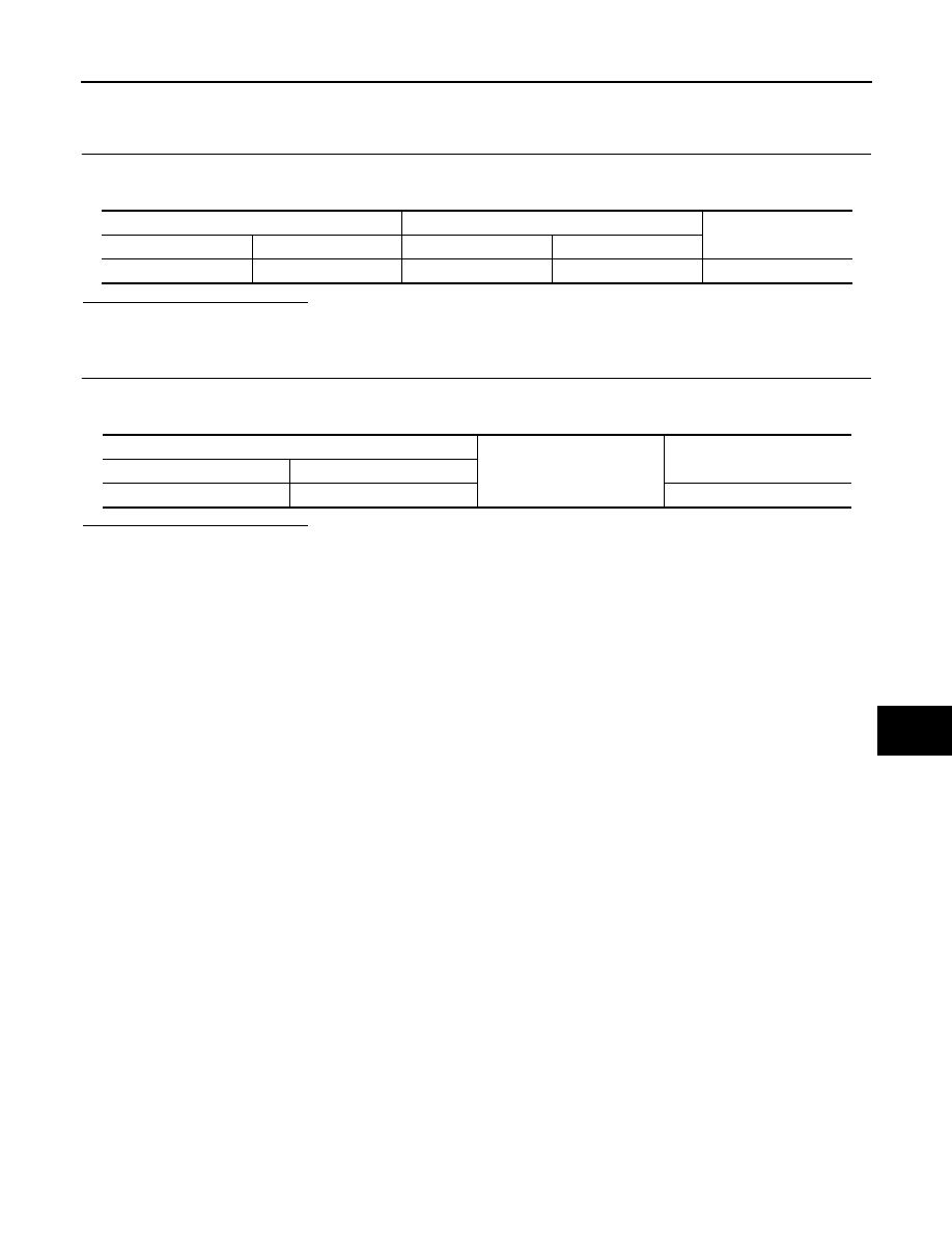
CHECK SUNSHADE MOTOR ASSEMBLY POWER SUPPLY CIRCUIT 2

Check continuity between circuit breaker harness connector and sunshade motor assembly harness connec-
tor.

Is the inspection result normal?

YES

>> Replace circuit breaker.

NO

>> Repair or replace harness.

6.

CHECK SUNSHADE MOTOR ASSEMBLY GROUND CIRCUIT

1.

Turn ignition switch OFF.

2.

Check continuity between sunshade motor assembly harness connector and ground.

Is the inspection result normal?

YES

>> INSPECTION END

NO

>> Repair or replace harness.

Circuit breaker

Sunshade motor assembly

Continuity

Connector

Terminal

 Connector

Terminal

M86

2

R11

7

Existed

Sunshade motor assembly

Ground

Continuity 

 Connector

Terminal

R11

1

Existed

RF-18

< DTC/CIRCUIT DIAGNOSIS >

SUNSHADE SWITCH

SUNSHADE SWITCH

Component Function Check

INFOID:0000000010286639

1.

CHECK FUNCTION

Check sunshade open and close operations with sunshade switch.
Is the inspection result normal?

YES

>> INSPECTION END

NO

>> Refer to 

RF-18, "Diagnosis Procedure"

.

Diagnosis Procedure

INFOID:0000000010286640

1.

CHECK SUNSHADE SWITCH INPUT SIGNAL 

1.

Turn ignition switch OFF.

2.

Disconnect sunshade switch connector.

3.

Turn ignition switch ON.

4.

Check voltage between sunshade switch harness connector and ground.

Is the inspection result normal?

YES

>> GO TO 3.

NO

>> GO TO 2.

2.

CHECK SUNSHADE SWITCH CIRCUIT

1.

Turn ignition switch OFF.

2.

Disconnect sunshade motor assembly connector.

3.

Check continuity between sunshade switch harness connector and sunshade motor assembly harness
connector.

4.

Check continuity between sunshade switch harness connector and ground. 

Is the inspection result normal?

YES

>> Replace sunshade motor assembly. Refer to 

RF-30, "Removal and Installation"

.

NO

>> Repair or replace harness.

3.

CHECK SUNSHADE SWITCH GROUND CIRCUIT

1.

Turn ignition switch OFF.

2.

Check continuity between sunshade switch harness connector and ground.

(+)

(

)

Voltage

Sunshade switch

Connector

Terminal

R16

1

Ground

9 - 16 V

3

Sunshade switch

Sunshade motor assembly

Continuity

Connector

Terminal

 Connector

Terminal

R16

1

R11

8

Existed

3

6

Sunshade switch

Ground

Continuity

 Connector

Terminal

R16

1

Not existed

3

SUNSHADE SWITCH

RF-19

< DTC/CIRCUIT DIAGNOSIS >

C

D

E

F

G

H

I

J

L

M

A

B

RF

N

O

P

Is the inspection result normal?

YES

>> GO TO 4.

NO

>> Repair or replace harness or connector.

4.

CHECK SUNSHADE SWITCH

Check sunshade switch.
Refer to 

RF-19, "Component Inspection"

.

Is the inspection result normal?

YES

>> Check intermittent incident. Refer to 

GI-44, "Intermittent Incident"

.

NO

>> Replace sunshade switch. Refer to 

RF-35, "Removal and Installation"

.

Component Inspection

INFOID:0000000010286641

1.

CHECK SUNSHADE SWITCH

1.

Turn ignition switch OFF.

2.

Disconnect sunshade switch connector.

3.

Check continuity sunshade switch terminals under the following conditions.

Is the inspection result normal?

YES

>> INSPECTION END

NO

>> Replace sunshade switch. Refer to 

RF-35, "Removal and Installation"

.

Sunshade switch

Ground

Continuity 

 Connector

Terminal

R16

2

Existed

Terminal

Condition

Continuity

1

2

Sunshade switch

Open position

Existed

Other than the above

Not existed

3

Close position

Existed

Other than the above

Not existed

RF-20

< SYMPTOM DIAGNOSIS >

SUNSHADE DOES NOT OPERATE PROPERLY

SYMPTOM DIAGNOSIS

SUNSHADE DOES NOT OPERATE PROPERLY

Description

INFOID:0000000010286642

Sunshade does not operate normally.
• Sunshade does not slide.
• Judder occurs during sliding operation of sunshade.
• Sliding operation of sunshade is slow.

Diagnosis Procedure

INFOID:0000000010286643

1.

CHECK SUNSHADE MECHANISM

Check the following.
• Operation malfunction caused by sunshade mechanism deformation, pinched harness or other foreign

materials.

• Operation malfunction and interference with other parts by poor installation.

Is the inspection result normal?

YES

>> GO TO 2.

NO

>> Repair or replace the malfunctioning parts.

2.

CHECK SUNSHADE MOTOR ASSEMBLY POWER SUPPLY AND GROUND CIRCUIT

Check sunshade motor assembly power supply and ground circuit.
Refer to 

RF-16, "SUNSHADE MOTOR ASSEMBLY : Diagnosis Procedure"

.

Is the inspection result normal?

YES

>> GO TO 3.

NO

>> Repair or replace the malfunctioning parts.

3.

CHECK SUNSHADE SWITCH

Check sunshade switch.
Refer to 

RF-18, "Component Function Check"

.

Is the inspection result normal?

YES

>> Check intermittent incident. Refer to 

GI-44, "Intermittent Incident"

.

NO

>> Repair or replace the malfunctioning parts.

AUTO OPERATION DOES NOT OPERATE

RF-21

< SYMPTOM DIAGNOSIS >

C

D

E

F

G

H

I

J

L

M

A

B

RF

N

O

P

AUTO OPERATION DOES NOT OPERATE

Description

INFOID:0000000010286644

Auto operation does not operate
• Auto operation of sunshade does not operate.
• Sunshade stops halfway.
• Anti-pinch function operates.

Diagnosis Procedure

INFOID:0000000010286645

1.

CHECK SUNSHADE MECHANISM

Check the following.
• Operation malfunction caused by sunshade mechanism deformation, pinched harness or other foreign

materials.

• Operation malfunction and interference with other parts by poor installation.

Is the inspection result normal?

YES

>> GO TO 2.

NO

>> Repair or replace the malfunctioning parts.

2.

PERFORM INITIALIZATION PROCEDURE

Perform initialization procedure. 
Refer to 

RF-14, "Description"

.

Is the inspection result normal?

YES

>> Check intermittent incident. Refer to 

GI-44, "Intermittent Incident"

.

NO

>> Replace sunshade motor assembly. Refer to 

RF-30, "Removal and Installation"

.

RF-22

< SYMPTOM DIAGNOSIS >

SUNSHADE DOES NOT OPERATE ANTI-PINCH FUNCTION

SUNSHADE DOES NOT OPERATE ANTI-PINCH FUNCTION

Diagnosis Procedure

INFOID:0000000010286646

1.

PERFORM INITIALIZATION PROCEDURE

Perform initialization procedure. 
Refer to 

RF-14, "Description"

.

Is the inspection result normal?

YES

>> INSPECTION END

NO

>> Check intermittent incident. Refer to 

GI-44, "Intermittent Incident"

SQUEAK AND RATTLE TROUBLE DIAGNOSES

RF-23

< SYMPTOM DIAGNOSIS >

C

D

E

F

G

H

I

J

L

M

A

B

RF

N

O

P

SQUEAK AND RATTLE TROUBLE DIAGNOSES

Work Flow

INFOID:0000000010286648

CUSTOMER INTERVIEW

Interview the customer if possible, to determine the conditions that exist when the noise occurs. Use the Diag-
nostic Worksheet during the interview to document the facts and conditions when the noise occurs and any of
the customer's comments; refer to 

RF-27, "Diagnostic Worksheet"

. This information is necessary to duplicate

the conditions that exist when the noise occurs.
• The customer may not be able to provide a detailed description or the location of the noise. Attempt to obtain

all the facts and conditions that exist when the noise occurs (or does not occur).

• If there is more than one noise in the vehicle, be sure to diagnose and repair the noise that the customer is

concerned about. This can be accomplished by a test drive with the customer.   

• After identifying the type of noise, isolate the noise in terms of its characteristics. The noise characteristics

are provided so the customer, service adviser and technician are all speaking the same language when
defining the noise.

• Squeak – (Like tennis shoes on a clean floor)

Squeak characteristics include the light contact/fast movement/brought on by road conditions/hard surfaces
= higher pitch noise/softer surfaces = lower pitch noises/edge to surface = chirping 

• Creak – (Like walking on an old wooden floor)

Creak characteristics include firm contact/slow movement/twisting with a rotational movement/pitch depen-
dent on materials/often brought on by activity.

• Rattle – (Like shaking a baby rattle)

Rattle characteristics include the fast repeated contact/vibration or similar movement/loose parts/missing
clip or fastener/incorrect clearance.

• Knock – (Like a knock on a door)

Knock characteristics include hollow sounding/sometimes repeating/often brought on by driver action.

• Tick – (Like a clock second hand)

Tick characteristics include gentle contacting of light materials/loose components/can be caused by driver
action or road conditions.

• Thump – (Heavy, muffled knock noise)

Thump characteristics include softer knock/dead sound often brought on by activity.

• Buzz – (Like a bumble bee)

Buzz characteristics include high frequency rattle/firm contact.

• Often the degree of acceptable noise level will vary depending upon the person. A noise that a technician

may judge as acceptable may be very irritating to the customer.

• Weather conditions, especially humidity and temperature, may have a great effect on noise level.

DUPLICATE THE NOISE AND TEST DRIVE

If possible, drive the vehicle with the customer until the noise is duplicated. Note any additional information on
the Diagnostic Worksheet regarding the conditions or location of the noise. This information can be used to
duplicate the same conditions when the repair is reconfirmed.

SBT842

RF-24

< SYMPTOM DIAGNOSIS >

SQUEAK AND RATTLE TROUBLE DIAGNOSES

If the noise can be duplicated easily during the test drive, to help identify the source of the noise, try to dupli-
cate the noise with the vehicle stopped by doing one or all of the following:
1) Close a door.
2) Tap or push/pull around the area where the noise appears to be coming from.
3) Rev the engine.
4) Use a floor jack to recreate vehicle “twist”.
5) At idle, apply engine load (electrical load, half-clutch on M/T model, drive position on A/T model).
6) Raise the vehicle on a hoist and hit a tire with a rubber hammer.
• Drive the vehicle and attempt to duplicate the conditions the customer states exist when the noise occurs.
• If it is difficult to duplicate the noise, drive the vehicle slowly on an undulating or rough road to stress the

vehicle body.

LOCATE THE NOISE AND IDENTIFY THE ROOT CAUSE

1.

Narrow down the noise to a general area. To help pinpoint the source of the noise, use a listening tool
(Engine ear or mechanics stethoscope).

2.

Narrow down the noise to a more specific area and identify the cause of the noise by:

• Removing the components in the area that is are suspected to be the cause of the noise.

Do not use too much force when removing clips and fasteners, otherwise clips and fastener can be broken
or lost during the repair, resulting in the creation of new noise.

• Tapping or pushing/pulling the component that is are suspected to be the cause of the noise.

Do not tap or push/pull the component with excessive force, otherwise the noise will be eliminated only tem-
porarily.

• Feeling for a vibration by hand by touching the component(s) that is are suspected to be the cause of the

noise.

• Placing a piece of paper between components that are suspected to be the cause of the noise.
• Looking for loose components and contact marks.

Refer to 

RF-25, "Inspection Procedure"

.

REPAIR THE CAUSE 

• If the cause is a loose component, tighten the component securely.
• If the cause is insufficient clearance between components:
- separate components by repositioning or loosening and retightening the component, if possible.
- insulate components with a suitable insulator such as urethane pads, foam blocks, felt cloth tape or urethane

tape. These insulators are available through the authorized Nissan Parts Department.

CAUTION:

Never use excessive force as many components are constructed of plastic and may be damaged.
NOTE:
• URETHANE PADS

Insulates connectors, harness, etc.

• INSULATOR (Foam blocks)

Insulates components from contact. Can be used to fill space behind a panel.

• INSULATOR (Light foam block)
• FELT CLOTHTAPE

Used to insulate where movement does not occur. Ideal for instrument panel applications.
The following materials, not available through NISSAN Parts Department, can also be used to repair
squeaks and rattles.

• UHMW(TEFLON) TAPE 

Insulates where slight movement is present. Ideal for instrument panel applications.

• SILICONE GREASE

Used in place of UHMW tape that is be visible or does not fit.
Note: Will only last a few months.

• SILICONE SPRAY

Used when grease cannot be applied.

• DUCT TAPE

Used to eliminate movement.

CONFIRM THE REPAIR

Confirm that the cause of a noise is repaired by test driving the vehicle. Operate the vehicle under the same
conditions as when the noise originally occurred. Refer to the notes on the Diagnostic Worksheet.

SQUEAK AND RATTLE TROUBLE DIAGNOSES

RF-25

< SYMPTOM DIAGNOSIS >

C

D

E

F

G

H

I

J

L

M

A

B

RF

N

O

P

Inspection Procedure

INFOID:0000000010286649

Refer to Table of Contents for specific component removal and installation information.

INSTRUMENT PANEL

Most incidents are caused by contact and movement between:

1.

Cluster lid A and instrument panel

2.

Acrylic lens and combination meter housing

3.

Instrument panel to front pillar garnish

4.

Instrument panel to windshield

5.

Instrument panel mounting pins

6.

Wiring harnesses behind the combination meter 

7.

A/C defroster duct and duct joint

These incidents can usually be located by tapping or moving the components to duplicate the noise or by
pressing on the components while driving to stop the noise. Most of these incidents can be repaired by apply-
ing felt cloth tape or silicon spray (in hard to reach areas). Urethane pads can be used to insulate wiring har-
ness.

CAUTION:

Never use silicone spray to isolate a squeak or rattle. If the area is saturated with silicone, the recheck
of repair becomes impossible.

CENTER CONSOLE

Components to pay attention to include:

1.

Shifter assembly cover to finisher

2.

A/C control unit and cluster lid C

3.

Wiring harnesses behind audio and A/C control unit

The instrument panel repair and isolation procedures also apply to the center console.

DOORS

Pay attention to the following:

1.

Finisher and inner panel making a slapping noise

2.

Inside handle escutcheon to door finisher

3.

Wiring harnesses tapping 

4.

Door striker out of alignment causing a popping noise on starts and stops

Tapping or moving the components or pressing on them while driving to duplicate the conditions can isolate
many of these incidents. You can usually insulate the areas with felt cloth tape or insulator foam blocks to
repair the noise.

TRUNK

Trunk noises are often caused by a loose jack or loose items put into the trunk by the customer.
In addition look for following:

1.

Trunk lid dumpers out of adjustment

2.

Trunk lid striker out of adjustment 

3.

Trunk lid torsion bars knocking together

4.

A loose license plate or bracket

Most of these incidents can be repaired by adjusting, securing or insulating the item(s) or component(s) caus-
ing the noise.

SUNROOF/HEADLINING

Noises in the sunroof/headlining area can often be traced to one of the following:

1.

Sunroof lid, rail, linkage or seals making a rattle or light knocking noise

2.

Sunvisor shaft shaking in the holder

3.

Front or rear windshield touching headlining and squeaking 

Again, pressing on the components to stop the noise while duplicating the conditions can isolate most of these
incidents. Repairs usually consist of insulating with felt cloth tape.

RF-26

< SYMPTOM DIAGNOSIS >

SQUEAK AND RATTLE TROUBLE DIAGNOSES

SEATS

When isolating seat noise it is important to note the position the seat is in and the load placed on the seat
when the noise occurs. These conditions should be duplicated when verifying and isolating the cause of the
noise.
Cause of seat noise include: 
1.

Headrest rods and holder 

2.

A squeak between the seat pad cushion and frame 

3.

Rear seatback lock and bracket 

These noises can be isolated by moving or pressing on the suspected components while duplicating the con-
ditions under which the noise occurs. Most of these incidents can be repaired by repositioning the component
or applying urethane tape to the contact area.

UNDERHOOD

Some interior noise may be caused by components under the hood or on the engine wall. The noise is then
transmitted into the passenger compartment.
Causes of transmitted underhood noise include:
1.

Any component mounted to the engine wall

2.

Components that pass through the engine wall

3.

Engine wall mounts and connectors

4.

Loose radiator mounting pins

5.

Hood bumpers out of adjustment 

6.

Hood striker out of adjustment

These noises can be difficult to isolate since they cannot be reached from the interior of the vehicle. The best
method is to secure, move or insulate one component at a time and test drive the vehicle. Also, engine RPM
or load can be changed to isolate the noise. Repairs can usually be made by moving, adjusting, securing, or
insulating the component causing the noise.

SQUEAK AND RATTLE TROUBLE DIAGNOSES

RF-27

< SYMPTOM DIAGNOSIS >

C

D

E

F

G

H

I

J

L

M

A

B

RF

N

O

P

Diagnostic Worksheet

INFOID:0000000010286650

PIIB8740E

RF-28

< SYMPTOM DIAGNOSIS >

SQUEAK AND RATTLE TROUBLE DIAGNOSES

PIIB8742E

SUNSHADE MOTOR ASSEMBLY

RF-29

< REMOVAL AND INSTALLATION >

C

D

E

F

G

H

I

J

L

M

A

B

RF

N

O

P

REMOVAL AND INSTALLATION

SUNSHADE MOTOR ASSEMBLY

Exploded View

INFOID:0000000010286668

1.

Sunshade assembry

2.

Sunshade unit assembly

3.

Rear sunshade bracket RH

4.

Welt

5.

Rear sunshade bracket LH

6.

Sunshade motoer

JMKIB3238ZZ

RF-30

< REMOVAL AND INSTALLATION >

SUNSHADE MOTOR ASSEMBLY

Removal and Installation

INFOID:0000000010286669

REMOVAL

1.

Remove the headlining. Refer to 

INT-25, "Removal and Installation"

2.

Disconnect harness connectoer 

.

3.

Remove the sunshade motor mounting TORX bolts 

, and then

remove sunshade motor assembly 

.

INSTALLATION

Note the following item, and then install in the reverse order of removal.
NOTE:
After install the sunshade motor, perform additional service. Refer to 

RF-14, "Description"

.

JMKIB3269ZZ

SUNSHADE UNIT ASSEMBLY

RF-31

< REMOVAL AND INSTALLATION >

C

D

E

F

G

H

I

J

L

M

A

B

RF

N

O

P

SUNSHADE UNIT ASSEMBLY

Exploded View

INFOID:0000000010438449

Removal and Installation

INFOID:0000000010286671

REMOVAL

CAUTION:

1.

Sunshade assembry

2.

Sunshade unit assembly

3.

Rear sunshade bracket RH

4.

Welt

5.

Rear sunshade bracket LH

6.

Sunshade motoer

JMKIB3238ZZ

RF-32

< REMOVAL AND INSTALLATION >

SUNSHADE UNIT ASSEMBLY

• Always work with a helper.
• Fully open the sunshade before removal.
• Never operate sunshade motor assembly after removal.
• When taking sunshade unit assembly out, use cloths to protect the seats and trim from damage.

1.

Fully open the sunshade.

2.

Remove the headlining. Refer to 

INT-25, "Removal and Installation"

3.

Remove the sunshade motor assembly. Refer to 

RF-30, "Removal and Installation"

.

4.

Remove the harness clamp.

5.

Remove the TORX bolt.

6.

Remove the rear sunshade bracket.

7.

Remove the mounting bolt from the side rail.

8.

Remove the unit side bolts of the sunshade front bracket and loosen the body side bolts.

9.

Remove the bolt from the rear end, and then remove sunshade unit assembly.

10. Remove the sunshade from vehicle.

INSTALLATION

1.

Temporarily tighten the mounting bolts to the sunshade front bracket.

2.

Place the front end of the rail onto the sunshade front bracket.

3.

Temporarily tighten the mounting bolts to the rear end of sunshade unit assembly.

4.

Temporarily tighten the mounting bolts to the rear sunshade bracket.

5.

Tighten the installation points diagonally excluding the installation point of the sunshade bracket around
the roof.

6.

Tighten the sunshade front and rear bracket bolts, of the vehicle side, and then tighten the bolt of the rail
side.

7.

Tighten the mounting bolt to the rear end.

8.

Install the sunshade motor assembly. Refer to 

RF-30, "Removal and Installation"

.

9.

Install the headlining. Refer to 

INT-25, "Removal and Installation"

Disassembly and Assembly

INFOID:0000000010286672

DISASSEMBLY

1.

Remove sunshade motor assembly. Refer to 

RF-30, "Removal and Installation"

2.

Remove sunshade assembly. Refer to 

RF-33, "Removal and Installation"

ASSEMBLY

Assemble in the reverse order of disassembly.
NOTE:
After installation sunshade motor, perform additional service. Refer to 

RF-14, "Description"

.

SUNSHADE

RF-33

< REMOVAL AND INSTALLATION >

C

D

E

F

G

H

I

J

L

M

A

B

RF

N

O

P

SUNSHADE

Exploded View

INFOID:0000000010438750

Removal and Installation

INFOID:0000000010286674

REMOVAL

1.

Remove sunshade unit assembly. Refer to 

RF-31, "Removal and Installation"

.

1.

Sunshade assembry

2.

Sunshade unit assembly

3.

Rear sunshade bracket RH

4.

Welt

5.

Rear sunshade bracket LH

6.

Sunshade motoer

JMKIB3238ZZ

RF-34

< REMOVAL AND INSTALLATION >

SUNSHADE

2.

Remove sunshade guide bracket fixing screw 

 and then

remove sunshade guide bracket 

 from sunshede unit 

3.

Disengage sunshade fixing pawls, and then remove sunshade
from sunshade unit assembly.

INSTALLATION

Install in the reverse order of removal.

: Vehicle front

JMKIB3267ZZ

: Vehicle front

JMKIB3268ZZ

SUNSHADE SWITCH

RF-35

< REMOVAL AND INSTALLATION >

C

D

E

F

G

H

I

J

L

M

A

B

RF

N

O

P

SUNSHADE SWITCH

Removal and Installation

INFOID:0000000010286663

Removal

1.

Remove map lamp assembly. Refer to 

INL-70, "MAP LAMP : Removal and Installation"

.

2.

Disconnect sunshade switch connector 

 from map lamp

assembly .

3.

Remove sunshade switch fixing TROX screws 

, and then

remove sunshade switch 

 from map lamp assembly.

Installation

Install in the reverse order of removal.

JMKIB2991ZZ


Content      ..      1      2