Qashqai J11. Mirrors - part 4
MIR-50
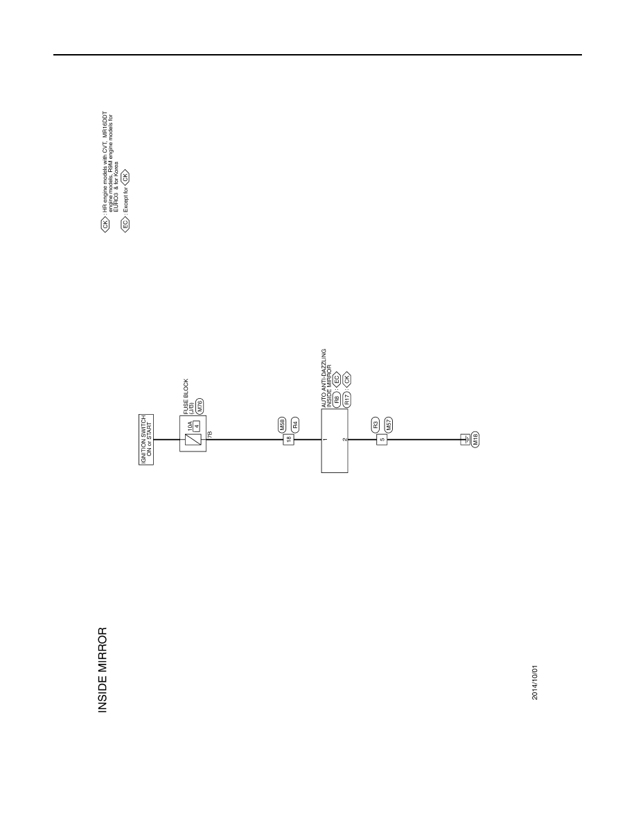
< WIRING DIAGRAM >
AUTO ANTI-DAZZLING MIRROR SYSTEM
AUTO ANTI-DAZZLING MIRROR SYSTEM
Wiring Diagram
INFOID:0000000010502665
JRLWE4139GB
|
|
|
MIR-50 < WIRING DIAGRAM > AUTO ANTI-DAZZLING MIRROR SYSTEM AUTO ANTI-DAZZLING MIRROR SYSTEM Wiring Diagram INFOID:0000000010502665 JRLWE4139GB |