Qashqai J11. Front axle - part 4
FRONT WHEEL HUB AND KNUCKLE
FAX-49
< REMOVAL AND INSTALLATION >
[4WD]
C
E
F
G
H
I
J
K
L
M
A
B
FAX
N
O
P
REMOVAL AND INSTALLATION
FRONT WHEEL HUB AND KNUCKLE
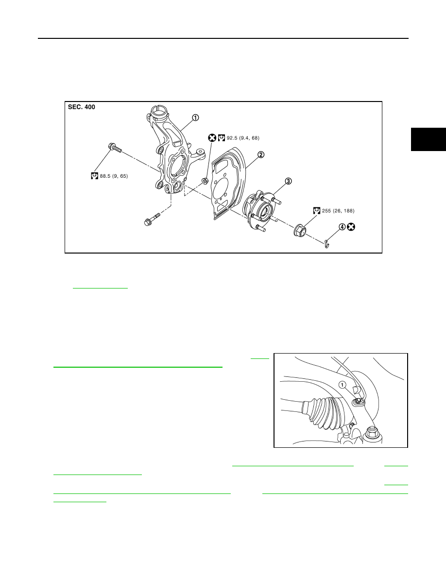
Exploded View
INFOID:0000000010297864
Removal and Installation
INFOID:0000000010297865
REMOVAL
Wheel hub
1.
emove tires from vehicle.
2.
Remove wheel sensor (1) from steering knuckle. Refer to
138, "FRONT WHEEL SENSOR : Exploded View"
CAUTION:
• Failure to separate the front wheel sensor from the steer-
ing knuckle may result in damage to the front wheel sen-
sor.
• Never pull on wheel sensor harness.
3.
Remove lock plate from strut assembly. Refer to
BR-19, "FRONT : Exploded View"
(LHD),
4.
Remove torque member mounting bolts. Hang torque member not to interfere with work. Refer to
"BRAKE CALIPER ASSEMBLY : Exploded View"
(LHD),
BR-80, "BRAKE CALIPER ASSEMBLY :
(RHD).
CAUTION:
Never depress brake pedal while brake caliper is removed.
5.
Remove disc rotor.
6.
Remove cotter pin, and then loosen hub lock nut.
1.
Steering knuckle
2.
Splash guard
3.
Wheel hub and bearing assembly
4.
Cotter pin
Refer to
E1DIA0224GB
ALDIA0526ZZ