Qashqai J11. Driveline - part 2


  Index      Nissan     Qashqai J11. Driveline. Service and Repair Manual


Search            copyright infringement  


Content      ..      1      2      3      ..


Qashqai J11. Driveline - part 2


SYSTEM

DLN-17

< SYSTEM DESCRIPTION >

[TRANSFER: TY21C]

C

E

F

G

H

I

J

K

L

M

A

B

DLN

N

O

P

If there is a significant difference in pressure or wear between tires, full vehicle performance is not available.
Tire conditions are detected, and LOCK mode may be prohibited, or else speeds at which LOCK mode is
enabled may be restricted.

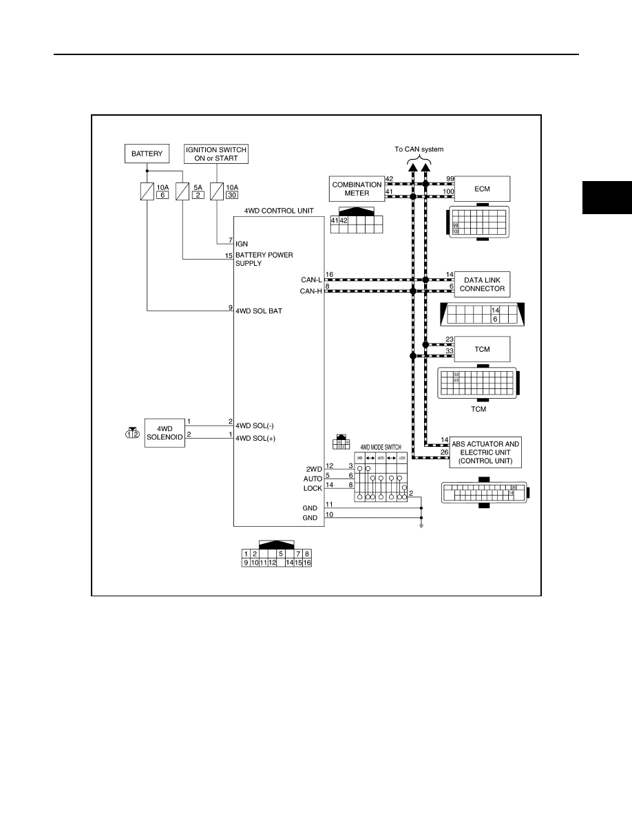
4WD SYSTEM : Circuit Diagram

INFOID:0000000010755233

4WD SYSTEM : Fail-Safe

INFOID:0000000010755234

If any malfunction occurs in 4WD electrical system, and control unit detects the malfunction, 4WD warning on
information display (combination meter) is displayed to indicate system malfunction. And then 4WD control
unit controls becomes the fail-safe mode depending on DTC.

JSDIA6027GB

DLN-18

< SYSTEM DESCRIPTION >

[TRANSFER: TY21C]

SYSTEM

4WD SYSTEM : Protection Function

INFOID:0000000010755235

4WD system activates its protection function (shuts down 4WD system temporarily) if 4WD system detects
high load continuously or the front wheel tire size differs from the rear tire size. (4WD system is automatically
restored if 4WD system no longer detects any overload or the tire size difference is eliminated.)

NOTE:
• If the 4WD warning displays during driving but remains not displayed after the engine is restarted, the syste-

mis normal. If it again displays after driving for some time, vehicle must be inspected.

• When there is a difference of revolution speed between the front and rear wheel the shift occasionally

changes to direct 4-wheel driving conditions automatically. This is not a malfunction.

INFORMATION DISPLAY (COMBINATION METER)

INFORMATION DISPLAY (COMBINATION METER) : 4WD Warning

INFOID:0000000010755236

DESIGN/PURPOSE

4WD warning is displayed when the 4WD system has a malfunction. 4WD warning indicates that the vehicle is
in fail-safe mode or protection function mode.

SYNCHRONIZATION WITH MASTER WARNING LAMP

Applicable
For master warning lamp, refer to 

WCS-7, "WARNING CHIME SYSTEM : System Description"

.

DTC

Vehicle condition

•C1201
•C1204
•C1209
•P1804
•P1809

•P1811

•P181F

4WD control changes to front-wheel drive immediately, then 4WD control stops, and the vehicle 
becomes front-wheel drive.

•C1203
•C1210
•P1808

•P181D

•U1000
•U1010

4WD control changes to front-wheel drive gradually (rear-wheels still have some driving torque), 
then 4WD control stops, and the vehicle becomes front-wheel drive.

•P181B

No impact to vehicle behavior.

DTC

4WD warning (on infor-

mation display)

Error area and root cause

Contents of protection 

function

Refer to 

DLN-18, "IN-

FORMATION DISPLAY 

(COMBINATION 

METER) : 4WD Warn-

ing"

.

Rear final drive assembly in protection mode. It is not malfunction.
(Internal temperature rise of electronic controlled coupling)

Shuts down 4WD sys-

tem temporarily

(Front wheel drive)

Malfunction in each tire or different tire diameter

Symbol

Message

Condition

4WD Error
See Owner’s Manual

4WD system malfunction.

4WD High Temp.
Stop vehicle

Protection function is activated due to heavy load to 
electric controlled coupling. (4WD system is not 
malfunctioning and 4WD system changes to front 
wheel drive.)

Tire Size Incorrect
See Owner’s Manual

Large difference in diameter of front/rear tires.

JPNIA1896ZZ

SYSTEM

DLN-19

< SYSTEM DESCRIPTION >

[TRANSFER: TY21C]

C

E

F

G

H

I

J

K

L

M

A

B

DLN

N

O

P

SYSTEM DIAGRAM

SIGNAL PATH

• The 4WD control unit judges and decides a mode from among normal mode, fail-safe mode, and protection

function mode, according to signals received from each switch, sensor, and control unit.

• The 4WD control unit transmits 4WD warning signal to the combination meter via CAN communication when

judging fail-safe mode or protection function mode.

• The combination meter displays 4WD warning on the information display when receiving 4WD warning sig-

nal transmitted from the 4WD control unit.

WARNING CONDITION

4WD warning is displayed when the 4WD system goes into fail-safe mode or protection function mode.

WARNING CANCEL CONDITION

When any of the conditions listed below is satisfied:
• Ignition switch is in a position other than ON.
• 4WD warning becomes invisible when the 4WD system returns to normal.

INFORMATION DISPLAY (COMBINATION METER) : 4WD Torque Distribution Indica-
tor

INFOID:0000000010755237

DESIGN/PURPOSE

WARNING/INDICATOR/CHIME LIST

WARNING/INDICATOR/CHIME LIST : Warning Lamp/Indicator Lamp

INFOID:0000000010755238

JSDIA6028GB

Design

Purpose

Displays the drive torque distribution to the front and rear wheels while driving and informs 
the driver of this.
NOTE:
The driving force distribution may not match actual one. This is not a system malfunction.

JSNIA6722ZZ

Name

Design

Layout/Function

4WD indicator lamp

For layout: Refer to 

WCS-5, "Component Parts Location"

.

For function: Refer to 

DLN-20, "WARNING/INDICATOR/CHIME LIST : Warning/Indica-

tor (On Information Display)"

.

DLN-20

< SYSTEM DESCRIPTION >

[TRANSFER: TY21C]

SYSTEM

WARNING/INDICATOR/CHIME LIST : Warning/Indicator (On Information Display)

INFOID:0000000010755239

LOCK indicator lamp

For layout: Refer to 

WCS-5, "Component Parts Location"

.

For function: Refer to 

DLN-20, "WARNING/INDICATOR/CHIME LIST : Warning/Indica-

tor (On Information Display)"

.

Name

Design

Layout/Function

Name

Function

4WD warning

Refer to 

DLN-18, "INFORMATION DISPLAY (COMBINATION METER) : 4WD Warn-

ing"

.

4WD torque distribution indicator

Refer to 

DLN-19, "INFORMATION DISPLAY (COMBINATION METER) : 4WD Torque 

Distribution Indicator"

.

DIAGNOSIS SYSTEM (4WD CONTROL UNIT)

DLN-21

< SYSTEM DESCRIPTION >

[TRANSFER: TY21C]

C

E

F

G

H

I

J

K

L

M

A

B

DLN

N

O

P

DIAGNOSIS SYSTEM (4WD CONTROL UNIT)

CONSULT Function

INFOID:0000000010755240

APPLICATION ITEMS

CONSULT can display each diagnostic item using the diagnostic test modes as follows.

*: The following diagnosis information is erased by erasing.
• DTC
• Freeze frame data (FFD)

ECU IDENTIFICATION

4WD control unit part number can be read.

SELF DIAGNOSTIC RESULT

Refer to 

DLN-26, "DTC Index"

.

When “PRSNT” is displayed on self-diagnosis result.

• The system is presently malfunctioning.

When “PAST” is displayed on self-diagnosis result.

• System malfunction in the past is detected, but the system is presently normal.

FREEZE FRAME DATA (FFD)

The following vehicle status is recorded when DTC is detected and is displayed.

Diagnostic test mode

Function

ECU Identification

4WD control unit part number can be read.

Self Diagnostic Result

Self-diagnostic results and freeze frame data can be read and erased quickly.*

Data Monitor

Input/Output data in the 4WD control unit can be read.

Active Test

Diagnostic Test Mode in which CONSULT drives some actuators apart from the 4WD control unit 
and also shifts some parameters in a specified range.

Work support

This mode enable a technician to adjust some devices faster and more accurately by following the 
indication on the CONSULT.

Monitor item (Unit)

Remarks

ODO/TRIP METER (km/h or mph)

Odometer value via CAN communication line is displayed.

ABS OPERATION SIG (On/Off)

ABS operation status via CAN communication line is displayed.

VDC OPERATION SIG (On/Off)

VDC operation status via CAN communication line is displayed.

TCS OPERATION SIG (On/Off)

TCS operation status via CAN communication line is displayed.

HI COEF FRIC FLG 1 (LOW/HIGH)

Measured friction of load is displayed when vehicle starts.

HI COEF FRIC FLG 2 (LOW/HIGH)

Measured friction of load is displayed when vehicle during deceleration.

IGN VOLT (V)

Ignition voltage supplied to 4WD control unit is displayed.

TARGET SOL CRNT (A)

4WD solenoid target current is displayed.

SOLENOID CRNT (A)

4WD solenoid control current is displayed.

QUASI VEHICLE SPEED (km/h or mph)

Vehicle speed calculated by 4WD control unit is displayed.

FRONT WHEEL SPEED (km/h or mph)

Front wheel speed average calculated by 4WD control unit is displayed.

REAR WHEEL SPEED (km/h or mph)

Rear wheel speed average calculated by 4WD control unit is displayed.

SLCT LVR POSI

Current transmission gear via CAN communication line is displayed.

OPERATION MODE

Control status of 4WD mode is displayed.

FRONT RH WHEEL SPEED (km/h or mph)

Wheel speed calculated by front RH wheel sensor signal is displayed.

FRONT LH WHEEL SPEED (km/h or mph)

Wheel speed calculated by front LH wheel sensor signal is displayed.

REAR RH WHEEL SPEED (km/h or mph)

Wheel speed calculated by rear RH wheel sensor signal is displayed.

REAR LH WHEEL SPEED (km/h or mph)

Wheel speed calculated by rear LH wheel sensor signal is displayed.

DLN-22

< SYSTEM DESCRIPTION >

[TRANSFER: TY21C]

DIAGNOSIS SYSTEM (4WD CONTROL UNIT)

DATA MONITOR

NOTE:
The following table includes information (items) inapplicable to this vehicle. For information (items) applicable
to this vehicle, refer to CONSULT display items.

ACTIVE TEST

Use this mode to determine and identify the details of a malfunction based on self-diagnostic results or data
monitor. 4WD control unit gives drive signal to actuator with receiving command from CONSULT to check
operation of actuator.

CAUTION:

Never energize continuously for a long time.

WORK SUPPORT

Monitor item (Unit)

Remarks

STOP LAMP SW (On/Off)

Stop lamp switch signal status via CAN communication line is displayed.

ENG SPEED SIG (Run/Stop)

Engine status is displayed.

ETS ACTUATOR (On/Off)

Operating condition of 4WD actuator relay (integrated in 4WD control unit) is displayed.

4WD WARN LAMP (On/Off)

Control status of 4WD warning (on information display) is displayed.

4WD MODE SW (AUTO/LOCK/2WD)

4WD mode switch status is displayed.

4WD MODE MON (AUTO/LOCK/2WD)

Control status of 4WD is displayed.

DIS-TIRE MONI (mm)

Improper size tire installed condition is displayed.

PARKING BRAKE SW SIG (On/Off)

Parking switch signal status via CAN communication line is displayed.

4WD MODE SW (2WD) (On/Off)

4WD mode switch (2WD position) signal is displayed.

4WD MODE SW (AUTO) (On/Off)

4WD mode switch (AUTO position) signal is displayed.

4WD MODE SW (LOCK) (On/Off)

4WD mode switch (LOCK position) signal is displayed.

READY (Off/Running)

This item is not equipped, but displayed.

BATTERY VOLT (V)

Power supply voltage value of 4WD control unit is displayed.

THRTL POS SEN (%)

Throttle opening status is displayed.

ETS SOLENOID (A)

Monitored value of current at 4WD solenoid is displayed.

FR RH SENSOR (km/h or mph)

Wheel speed calculated by front RH wheel sensor signal is displayed.

FR LH SENSOR (km/h or mph)

Wheel speed calculated by front LH wheel sensor signal is displayed.

RR RH SENSOR (km/h or mph)

Wheel speed calculated by rear RH wheel sensor signal is displayed.

RR LH SENSOR (km/h or mph)

Wheel speed calculated by rear LH wheel sensor signal is displayed.

Test item

Condition

Description

SOLENOID
(Detects 4WD solenoid)

• Vehicle stopped
• Engine running
• No DTC detected

Change command current value to 4WD solenoid, and then change driving 
mode. (Monitor value is normal if it is within approx. 

±

10% of command value.)

• Qu: Increase current value in increments of 0.2 A
• Qd: Decrease current value in increments of 0.2 A
• UP: Increase current value in increments of 0.02 A
• DOWN: Decrease current value in increments of 0.02 A

Item

Usage

UNIT CHARACTERISTICS DATA

Display the unit characteristics of electric controlled coupling written to 4WD control unit.

UNIT CHARACTERISTICS WRITE

Writes the unit characteristics of electric controlled coupling to 4WD control unit.

4WD CONTROL UNIT

DLN-23

< ECU DIAGNOSIS INFORMATION >

[TRANSFER: TY21C]

C

E

F

G

H

I

J

K

L

M

A

B

DLN

N

O

P

ECU DIAGNOSIS INFORMATION

4WD CONTROL UNIT

Reference Value

INFOID:0000000010755241

VALUES ON THE DIAGNOSIS TOOL

NOTE:
The following table includes information (items) inapplicable to this vehicle. For information (items) applicable
to this vehicle, refer to CONSULT display items.

Monitor item

Condition

Value/Status

STOP LAMP SW

Brake pedal: Depressed

On

Brake pedal: Released

Off

ENG SPEED SIG

Engine stopped
(Engine speed: Less than 400 rpm)

Stop

Engine running
(Engine speed: 400 rpm or more)

Run

ETS ACTUATOR

Engine stopped (Ignition switch: ON)

Off

Engine running

On

4WD WARN LAMP

4WD warning (on information display): Displayed

On

4WD warning (on information display): Not displayed

Off

4WD MODE SW

4WD mode switch: 2WD

2WD

4WD mode switch: AUTO

AUTO

4WD mode switch: LOCK
(State of hold of LOCK position)

LOCK

4WD MODE MON

4WD mode switch: 2WD

2WD

4WD mode switch: AUTO

AUTO

4WD mode switch: AUTO 

 LOCK

(When switching to LOCK mode)

Vehicle speed below 10 km/h (6 mph)

AUTO 

 LOCK

Vehicle speed above 10 km/h (6 mph)

AUTO

4WD mode switch: LOCK 

 AUTO

(When switching to AUTO mode)

Vehicle speed below 10 km/h (6 mph)

LOCK 

 AUTO

DIS-TIRE MONI

Vehicle running with normal size tire installed

0 – 4 mm

Vehicle running with improper size tire installed (Front/rear tire size differ-
ence, wear condition)

4 – 8 mm, 8 – mm

PARKING BRAKE SW 
SIG

Parking brake operated

On

Parking brake not operated

Off

4WD MODE SW (2WD)

4WD mode switch: 2WD

On

4WD mode switch: Except 2WD

Off

4WD MODE SW (AUTO)

4WD mode switch: AUTO

On

4WD mode switch: Except AUTO

Off

4WD MODE SW (LOCK)

4WD mode switch: LOCK
(State of hold of LOCK position)

On

4WD mode switch: Except LOCK

Off

READY

Always

Off

BATTERY VOLT

Always

Battery voltage

THRTL POS SEN

When depressing accelerator pedal
(Value rises gradually in response to throttle position.)

0 – 100%

DLN-24

< ECU DIAGNOSIS INFORMATION >

[TRANSFER: TY21C]

4WD CONTROL UNIT

*: The values are changed by throttle opening and engine speed.

TERMINAL LAYOUT

PHYSICAL VALUES

ETS SOLENOID

Engine running
• At idle speed

2WD mode

Approx. 0.000 A

AUTO mode

Approx. 0.000 A

LOCK mode

Approx. 0.000 A

Engine running
• 3,000 rpm or more constant

2WD mode

Approx. 0.000 A

AUTO mode

Approx. 0.000 – 2.490 A*

LOCK mode

Approx. 2.490 A

FR RH SENSOR

Vehicle stopped

0.00 km/h (0.00 mph)

Vehicle running

CAUTION:

Check air pressure of tire under standard condition.

Nearly matches the speed 
meter display (

±

10% or 

less)

FR LH SENSOR

Vehicle stopped

0.00 km/h (0.00 mph)

Vehicle running

CAUTION:

Check air pressure of tire under standard condition.

Nearly matches the speed 
meter display (

±

10% or 

less)

RR RH SENSOR

Vehicle stopped

0.00 km/h (0.00 mph)

Vehicle running

CAUTION:

Check air pressure of tire under standard condition.

Nearly matches the speed 
meter display (

±

10% or 

less)

RR LH SENSOR

Vehicle stopped

0.00 km/h (0.00 mph)

Vehicle running

CAUTION:

Check air pressure of tire under standard condition.

Nearly matches the speed 
meter display (

±

10%)

Monitor item

Condition

Value/Status

JSDIA0057ZZ

Terminal No.

(Wire color)

Description

Condition

Value (Approx.)

+

-

Signal name

Input/

Output

1

(SB)

Ground

4WD solenoid power 
supply

Output

Engine speed: At idle

2WD mode

0 V

AUTO mode

0 V

LOCK mode

0 V

Engine speed: 3,000 
rpm or more constant

2WD mode

0 V

AUTO mode

2.5 V*

LOCK mode

8 V

2

(Y)

Ground

4WD solenoid ground

Input

Engine speed: At idle

0 V

Engine speed: 3,000 rpm or more constant

0 V

4WD CONTROL UNIT

DLN-25

< ECU DIAGNOSIS INFORMATION >

[TRANSFER: TY21C]

C

E

F

G

H

I

J

K

L

M

A

B

DLN

N

O

P

*: The values are changed by depressed accelerator pedal opening and engine speed.

CAUTION:

When using circuit tester to measure voltage for inspection, be sure not to extend forcibly any con-
nector terminals.

Fail-Safe

INFOID:0000000010755242

If any malfunction occurs in 4WD electrical system, and control unit detects the malfunction, 4WD warning on
information display (combination meter) is displayed to indicate system malfunction. And then 4WD control
unit controls becomes the fail-safe mode depending on DTC.

5

(V)

Ground

4WD mode switch (AU-
TO)

Input

Ignition switch: ON

4WD mode switch: 2WD

Battery voltage

4WD mode switch: AUTO

0 V

4WD mode switch: LOCK
(State of hold of LOCK position)

0 V

7

(LA/R)

Ground

Ignition switch

Input

Ignition switch: ON

Battery voltage

Ignition switch: OFF

0 V

8

(L)

CAN-H

Input/

Output

9

(LA/G)

Ground

Power supply (4WD so-
lenoid)

Input

Always

Battery voltage

10

(B)

Ground

Ground

Always

0 V

11

(B)

Ground

Ground

Always

0 V

12

(GR)

Ground

4WD mode switch 
(2WD)

Input

Ignition switch: ON

4WD mode switch: 2WD

0 V

4WD mode switch: AUTO

Battery voltage

4WD mode switch: LOCK
(State of hold of LOCK position)

Battery voltage

14

(Y)

Ground

4WD mode switch 
(LOCK)

Input

Ignition switch: ON

4WD mode switch: 2WD

Battery voltage

4WD mode switch: AUTO

Battery voltage

4WD mode switch: LOCK
(State of hold of LOCK position)

0 V

15

(LA/L)

Ground

Power supply (4WD 
control unit)

Input

Always

Battery voltage

16

(P)

CAN-L

Input/

Output

Terminal No.

(Wire color)

Description

Condition

Value (Approx.)

+

-

Signal name

Input/

Output

DTC

Vehicle condition

•C1201
•C1204
•C1209
•P1804
•P1809

•P1811

•P181F

4WD control changes to front-wheel drive immediately, then 4WD control stops, and the vehicle 
becomes front-wheel drive.

DLN-26

< ECU DIAGNOSIS INFORMATION >

[TRANSFER: TY21C]

4WD CONTROL UNIT

Protection Function

INFOID:0000000010755243

4WD system activates its protection function (shuts down 4WD system temporarily) if 4WD system detects
high load continuously or the front wheel tire size differs from the rear tire size. (4WD system is automatically
restored if 4WD system no longer detects any overload or the tire size difference is eliminated.)

NOTE:
• If the 4WD warning displays during driving but remains not displayed after the engine is restarted, the syste-

mis normal. If it again displays after driving for some time, vehicle must be inspected.

• When there is a difference of revolution speed between the front and rear wheel the shift occasionally

changes to direct 4-wheel driving conditions automatically. This is not a malfunction.

DTC Inspection Priority Chart

INFOID:0000000010755244

If some DTCs are displayed at the same time, perform inspections one by one based on the following priority
chart.

DTC Index

INFOID:0000000010755245

•C1203
•C1210
•P1808

•P181D

•U1000
•U1010

4WD control changes to front-wheel drive gradually (rear-wheels still have some driving torque), 
then 4WD control stops, and the vehicle becomes front-wheel drive.

•P181B

No impact to vehicle behavior.

DTC

Vehicle condition

DTC

4WD warning (on infor-

mation display)

Error area and root cause

Contents of protection 

function

Refer to 

DLN-18, "IN-

FORMATION DISPLAY 

(COMBINATION 

METER) : 4WD Warn-

ing"

.

Rear final drive assembly in protection mode. It is not malfunction.
(Internal temperature rise of electronic controlled coupling)

Shuts down 4WD sys-

tem temporarily

(Front wheel drive)

Malfunction in each tire or different tire diameter

Priority

Detected items (DTC)

1

• C1201 CONTROLLER FAILURE

2

• U1000 CAN COMM CIRCUIT
• U1010 CONTROL UNIT (CAN)

3

• C1203 ABS SYSTEM
• C1210 ENGINE SIGNAL 1
• P1808 VHCL SPEED SEN-ABS
• P181D ENGINE SYSTEM

4

• P1809 CONTROL UNIT

5

• C1204 4WD SOLENOID
• P1811 BATTERY VOLTAGE

6

• C1209 MODE SW

7

• P1804 CONTROL UNIT

8

• P181B INCOMP SELFSHUT
• P181F INCOMP CALIBRATION

DTC

Display Item

Reference

C1201

CONTROLLER FAILURE

DLN-38, "DTC Description"

C1203

ABS SYSTEM

DLN-39, "DTC Description"

C1204

4WD SOLENOID

DLN-40, "DTC Description"

4WD CONTROL UNIT

DLN-27

< ECU DIAGNOSIS INFORMATION >

[TRANSFER: TY21C]

C

E

F

G

H

I

J

K

L

M

A

B

DLN

N

O

P

NOTE:
If some DTCs are displayed at the same time, refer to 

DLN-26, "DTC Inspection Priority Chart"

.

C1209

MODE SW

DLN-43, "DTC Description"

C1210

ENGINE SIGNAL 1

DLN-46, "DTC Description"

P1804

CONTROL UNIT

DLN-47, "DTC Description"

P1808

VHCL SPEED SEN-ABS

DLN-48, "DTC Description"

P1809

CONTROL UNIT

DLN-49, "DTC Description"

P1811

BATTERY VOLTAGE

DLN-50, "DTC Description"

P181B

INCOMP SELF SHUT

DLN-53, "DTC Description"

P181D

ENGINE SYSTEM

DLN-56, "DTC Description"

P181F

INCOMP CALIBRATION

DLN-57, "DTC Description"

U1000

CAN COMM CIRCUIT

DLN-58, "DTC Description"

U1010

CONTROL UNIT (CAN)

DLN-59, "DTC Description"

DTC

Display Item

Reference

DLN-28

< WIRING DIAGRAM >

[TRANSFER: TY21C]

4WD SYSTEM

WIRING DIAGRAM

4WD SYSTEM

Wiring Diagram

INFOID:0000000010755246

JRDWC2498GB

4WD SYSTEM

DLN-29

< WIRING DIAGRAM >

[TRANSFER: TY21C]

C

E

F

G

H

I

J

K

L

M

A

B

DLN

N

O

P

JRDWC2519GB

DLN-30

< WIRING DIAGRAM >

[TRANSFER: TY21C]

4WD SYSTEM

JRDWC2520GB

4WD SYSTEM

DLN-31

< WIRING DIAGRAM >

[TRANSFER: TY21C]

C

E

F

G

H

I

J

K

L

M

A

B

DLN

N

O

P

JRDWC2521GB

DLN-32

< WIRING DIAGRAM >

[TRANSFER: TY21C]

4WD SYSTEM

JRDWC2522GB


Content      ..      1      2      3      ..