Qashqai J11. Body repair - part 16


  Index      Nissan     Qashqai J11. Body repair manual


Search            copyright infringement  


Content      ..     14      15      16      17     ..


Qashqai J11. Body repair - part 16


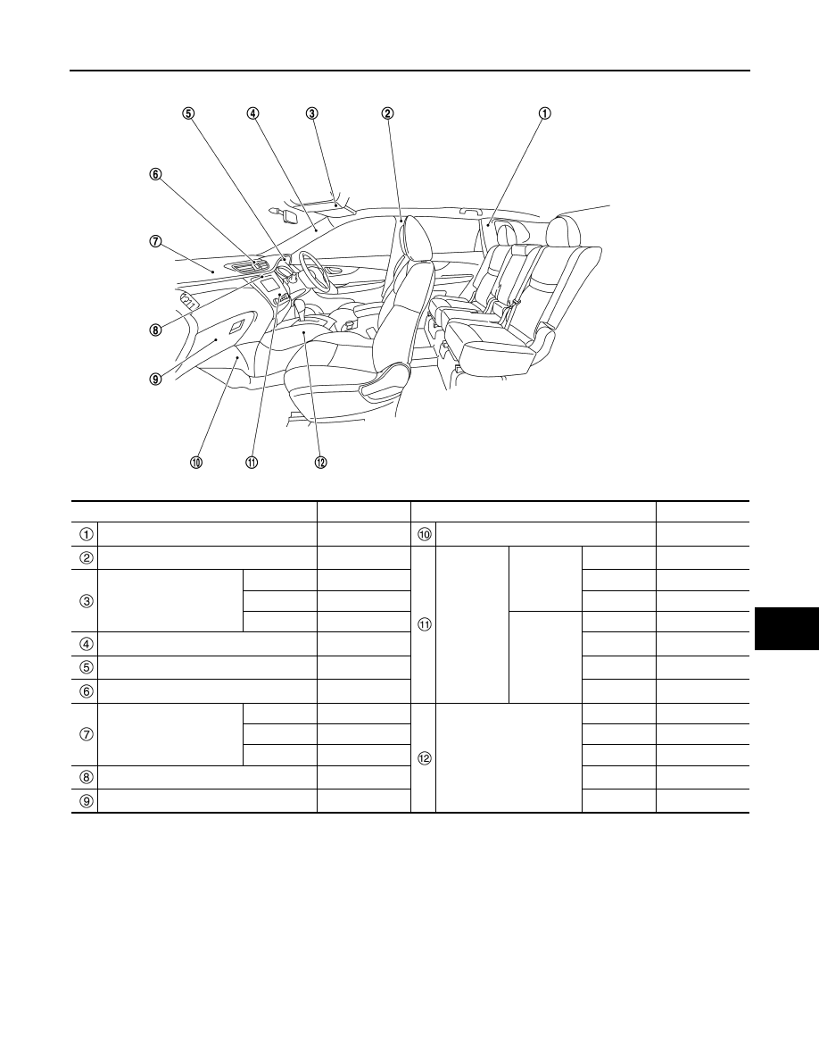
LOCATION OF PLASTIC PARTS

BRM-241

< SERVICE DATA AND SPECIFICATIONS (SDS) 

[FOR EUROPE (RHD)]

C

D

E

F

G

H

I

J

L

M

A

B

BRM

N

O

P

Component

Material

Component

Material

Rear pillar finisher

PP

Instrument lower cover

PP + EPDM

Center pillar garnish

PP

A/C Control

Manual A/C

Finisher

PC + ABS

Map lamp

Lens

PC

Switch

PC

Housing

PP

Case

ABS

Finisher

PP

Auto A/C

Finisher

PC + ABS

Front pillar garnish

PP

Switch

PC

Cluster lid A

PP

Case

PC + ABS

Center ventilator finisher

PC + ABS

Lens

PC

Instrument panel

Skin

TPO

Center console

Body

PP + EPDM

Pad

PUR

Console box

PP

Core

PP + EPDM

Inner lid

PP + EPDM

Cluster lid C

PC + ABS

Insert lid

PC + ABS

Glove box

PP

Cup holder

PP + EPDM

JSKIA3978ZZ

BRM-242

< VEHICLE INFORMATION >

[FOR RUSSIA]

BODY EXTERIOR PAINT COLOR

VEHICLE INFORMATION

BODY EXTERIOR PAINT COLOR

Body Exterior Paint Color

INFOID:0000000010498954

NOTE:

• S: 1-Coat solid

• 2M: 2-Coat Metallic

• 2S: 2-Coat solid

• 3P: 3-Coat pearl

• 2PM: 2-Coat Pearl metallic

Component

Color code

B326

BZ11

BKY0

BGAB

BKAD

BNAJ

BCAP

BRBN

BZ10

BQAB

Description

White

Black

Silver

Black

Gray

Red

Brown

Blue

Red

White

Paint type

 note

S

2M

2M

2M

2M

2PM

2M

2M

2S

3P

Standard 
clear coat

×

×

×

×

×

×

×

×

×

Door mirror cover

Body color

B326

BZ11

BKY0

BGAB

BKAD

BNAJ

BCAP

BRBN

BZ10

BQAB

Front grille molding

Chromium 
plate

Cr

Cr

Cr

Cr

Cr

Cr

Cr

Cr

Cr

Cr

Front bumper fascia

Body color

B326

BZ11

BKY0

BGAB

BKAD

BNAJ

BCAP

BRBN

BZ10

BQAB

Fillet  molding

Material  color

Door outside handle

Chromium 
plate

Cr

Cr

Cr

Cr

Cr

Cr

Cr

Cr

Cr

Cr

Rear spoiler

Body color

B326

BZ11

BKY0

BGAB

BKAD

BNAJ

BCAP

BRBN

BZ10

BQAB

Back door finisher

Body color

B326

BZ11

BKY0

BGAB

BKAD

BNAJ

BCAP

BRBN

BZ10

BQAB

Rear bumper fascia

Body color

B326

BZ11

BKY0

BGAB

BKAD

BNAJ

BCAP

BRBN

BZ10

BQAB

Door outside lower 
molding

Material  color

JSKIA3881ZZ

PRECAUTIONS

BRM-243

< PRECAUTION >

[FOR RUSSIA]

C

D

E

F

G

H

I

J

L

M

A

B

BRM

N

O

P

PRECAUTION

PRECAUTIONS

Precautions for Removing Battery Terminal

INFOID:0000000010503255

• With the adoption of Auto ACC function, ACC power is automatically supplied by operating the intelligent key

or remote keyless entry or by opening/closing the driver side door. In addition, ACC power is supplied even
after the ignition switch is turned to the OFF position, i.e. ACC power is supplied for a certain fixed time.

• When disconnecting the 12V battery terminal, turn off the ACC

power before disconnecting the 12V battery terminal, observing
“How to disconnect 12V battery terminal” described below.
NOTE:
Some ECUs operate for a certain fixed time even after ignition
switch is turned OFF and ignition power supply is stopped. If the
battery terminal is disconnected before ECU stops, accidental DTC
detection or ECU data damage may occur.

•  For vehicles with the 2-batteries, be sure to connect the main bat-

tery and the sub battery before turning ON the ignition switch.
NOTE:
If the ignition switch is turned ON with any one of the terminals of
main battery and sub battery disconnected, then DTC may be detected.

•  After installing the 12V battery, always check "Self Diagnosis Result" of all ECUs and erase DTC.

NOTE:
The removal of 12V battery may cause a DTC detection error.

HOW TO DISCONNECT 12V BATTERY TERMINAL

Disconnect 12V battery terminal according to Instruction 1 or Instruction 2 described below.
For vehicles parked by ignition switch OFF, refer to Instruction 2.

INSTRUCTION 1

1.

Open the hood.

2.

Turn key switch to the OFF position with the driver side door opened.

3.

Get out of the vehicle and close the driver side door.

4.

Wait at least 3 minutes. For vehicle with the engine listed below, remove the battery terminal after a lapse
of the specified time.

CAUTION:

While waiting, never operate the vehicle such as locking, opening, and closing doors. Violation of
this caution results in the activation of ACC power supply according to the Auto ACC function.

5.

Remove 12V battery terminal.

CAUTION:

After installing 12V battery, always check self-diagnosis results of all ECUs and erase DTC.

INSTRUCTION 2 (FOR VEHICLES PARKED BY IGNITION SWITCH OFF)

1.

Unlock the door with intelligent key or remote keyless entry.
NOTE:
At this moment, ACC power is supplied.

2.

Open the driver side door.

3.

Open the hood.

4.

Close the driver side door.

5.

Wait at least 3 minutes.

SEF289H

D4D engine

: 20 minutes

HRA2DDT

: 12 minutes

K9K engine

: 4 minutes

M9R engine

: 4 minutes

R9M engine

: 4 minutes

V9X engine

: 4 minutes

BRM-244

< PRECAUTION >

[FOR RUSSIA]

PRECAUTIONS

CAUTION:

While waiting, never operate the vehicle such as locking, opening, and closing doors. Violation of
this caution results in the activation of ACC power supply according to the Auto ACC function.

6.

Remove 12V battery terminal.

CAUTION:

After installing 12V battery, always check self-diagnosis results of all ECUs and erase DTC.

REPAIRING HIGH STRENGTH STEEL

BRM-245

< PRECAUTION >

[FOR RUSSIA]

C

D

E

F

G

H

I

J

L

M

A

B

BRM

N

O

P

REPAIRING HIGH STRENGTH STEEL

High Strength Steel (HSS)

INFOID:0000000010308851

High strength steel is used for body panels in order to reduce vehicle weight.
Accordingly, precautions in repairing automotive bodies made of high strength steel are described below:

Tensile strength

Major applicable parts

440 - 780 MPa

• Rear side floor

(Rear floor rear side component part) 

• Rear seat crossmember reinforcement assembly
• Trans control reinforcement

(Center front floor component part) 

• Front side member center extension

(Front floor component part) 

• 2nd and 3rd crossmember

(Front floor component part) 

• Inner sill
• Lower dash
• Lower dash crossmember
• Upper front hoodledge
• Front hoodledge reinforcement
• Hoodledge reinforcement
• Front strut housing
• Front side member closing plate assembly
• Front side member center closing plate
• Front side member front closing plate
• Front side member assembly
• Add on frame bracket
• Front side member front extension
• Front side member outrigger

(Front side member outrigger assembly component part) 

• Rear seat crossmember

(Rear seat crossmember component part) 

• Rear floor belt anchor reinforcement
• Rear side member front

(Rear side member assembly component part) 

• Rear side member rear
• Rear side member extension
• Rear roof rail
• Inner side roof rail
• Front roof rail brace
• Inner center pillar (Lower)

(Inner center pillar component part) 

• Center pillar reinforcement (Lower)

(Center pillar reinforcement component part) 

• Front pillar hinge brace

(Front pillar brace component part) 

• Outer sill reinforcement
• Rear roof rail brace

(Inner rear pillar component part) 

• Outer rear wheelhouse extension (Rear)

(Outer rear wheelhouse extension component part) 

BRM-246

< PRECAUTION >

[FOR RUSSIA]

REPAIRING HIGH STRENGTH STEEL

Read the following precautions when repairing HSS:

1.

Additional points to consider
• The repair of reinforcements (such as side members) by heat-

ing is not recommended, because it may weaken the compo-
nent. When heating is unavoidable, never heat HSS parts
above 550

°

C (1,022

°

F).

Verify heating temperature with a thermometer.
(Crayon-type and other similar type thermometer are appropri-
ate.)

• When straightening body panels, use caution in pulling any HSS panel. Because HSS is very strong,

pulling may cause deformation in adjacent sections of the body. In this case, increase the number of
measuring points, and carefully pull the HSS panel.

• When cutting HSS panels, avoid gas (torch) cutting if possible.

Instead, use a saw to avoid weakening surrounding areas due
to heat. If gas (torch) cutting is unavoidable, allow a minimum
margin of 50 mm (1.97 in).

Tensile strength

Major applicable parts

980 - 1350 MPa

• Front side member stiffener

(Front floor component part) 

• Center sill reinforcement

(Inner sill component part) 

• Outrigger reinforcement

(Front side member outrigger assembly component part) 

• Front side member rear extension
• Rear side member rear reinforcement

(Rear side member assembly component part) 

• Front roof rail
• Roof reinforcement assembly
• Side roof reinforcement
• Inner center pillar (Upper)

(Inner center pillar component part) 

• Center pillar seat belt anchor

(Inner center pillar component part) 

• Outer side roof rail reinforcement
• Center pillar reinforcement (Upper)

(Center pillar reinforcement component part) 

• Center pillar seat belt reinforcement

(Center pillar reinforcement component part) 

• Center sill reinforcement

(Outer sill reinforcement component part) 

• Outer rear sill reinforcement

(Outer rear wheelhouse extension component part) 

PIIA0115E

PIIA0117E

REPAIRING HIGH STRENGTH STEEL

BRM-247

< PRECAUTION >

[FOR RUSSIA]

C

D

E

F

G

H

I

J

L

M

A

B

BRM

N

O

P

• When welding HSS panels, use spot welding whenever possi-

ble in order to minimize weakening surrounding areas due to
heat.
If spot welding is impossible, use MIG. welding. Do not use
gas (torch) for welding because it is inferior in welding
strength.

• Spot welding on HSS panels is harder than that of an ordinary

steel panel.
Therefore, when cutting spot welds on a HSS panel, use a low
speed high torque drill (1,000 to 1,200 rpm) to increase drill bit
durability and facilitate the operation.

2.

Precautions in spot welding HSS
This work should be performed under standard working condi-
tions. Always note the following when spot welding HSS:
• The electrode tip diameter must be sized properly according to

the metal thickness.

• The panel surfaces must fit flush to each other, leaving no

gaps.

PIIA0144E

PIIA0145E

PIIA0146E

PIIA0147E

BRM-248

< PRECAUTION >

[FOR RUSSIA]

REPAIRING HIGH STRENGTH STEEL

• Follow the specifications for the proper welding pitch.

Unit: mm (in)

Thickness (T)

Minimum pitch (L)

0.6 (0.024)
0.8 (0.031)
1.0 (0.039)
1.2 (0.047)
1.6 (0.063)
1.8 (0.071)

10 (0.39) or more
12 (0.47) or more
18 (0.71) or more
20 (0.79) or more
27 (1.06) or more
31 (1.22) or more

JSKIA0781ZZ

REPAIRING MATERIAL

BRM-249

< PREPARATION >

[FOR RUSSIA]

C

D

E

F

G

H

I

J

L

M

A

B

BRM

N

O

P

PREPARATION

REPAIRING MATERIAL

Foam Repair

INFOID:0000000010308853

During factory body assembly, foam insulators are installed in certain body panels and locations around the
vehicle. Use the following procedure(s) to replace any factory-installed foam insulators.

URETHANE FOAM APPLICATIONS

Use commercially available Urethane foam for sealant (foam material) repair of material used on vehicle.

Read instructions on product for fill procedures.

Example of foaming agent filling operation procedure

1.

Fill procedures after installation of service part.

a.

Eliminate foam material remaining on vehicle side.

b.

Clean area after eliminating form insulator and foam material.

c.

Install service part.

d.

Insert nozzle into hole near fill area and fill foam material or fill enough to close gap with the service part.

2.

Fill procedures before installation of service part.

a.

Eliminate foam material remaining on vehicle side.

b.

Clean area after eliminating foam insulator and foam material.

c.

Fill foam material on wheelhouse outer side.

<Urethane foam for foaming agent>

3M™ Automix™ Flexible Foam 08463 or equiva-
lent

Urethane foam

Nozzle insert hole

: Vehicle front

JSKIA0129GB

BRM-250

< PREPARATION >

[FOR RUSSIA]

REPAIRING MATERIAL

NOTE:
Fill enough to close gap with service part while avoiding flange
area.

d.

Install service part.
NOTE:
Refer to label for information on working times.

Urethane foam

Fill while avoiding flange area

: Vehicle front

JSKIA0130GB

BODY COMPONENT PARTS

BRM-251

< PREPARATION >

[FOR RUSSIA]

C

D

E

F

G

H

I

J

L

M

A

B

BRM

N

O

P

BODY COMPONENT PARTS

Ultra High Strength Steel Part

INFOID:0000000010505348

DESCRIPTION

Ultra high strength steel parts signify high strength steel plates with tensile strength of 980 MPa or more.
When replacing parts made of ultra high strength steel or parts including ultra high strength steel, never per-
form the prohibition described below:

PROHIBITION

WARNING:

Never cut ultra high strength steel parts or perform butt welding. Violation of this prohibition causes
extreme strength degradation, and the strength before damage cannot be secured.

PART REPLACEMENT

To replace an ultra high strength part, be sure to replace it by panel supply unit of ultra high strength steel part.
For the welding method, refer to 

BRM-269, "Welding of Ultra High Strength Steel"

Underbody Component Parts

INFOID:0000000010499715

Refer to parts catalogue for the replacement parts.

BRM-252

< PREPARATION >

[FOR RUSSIA]

BODY COMPONENT PARTS

R9M engine models

: Both sided anti-corrosive precoated steel sections

: High strength steel (HSS) sections

: Both sided anti-corrosive steel and HSS sections

JSKIA3885ZZ

BODY COMPONENT PARTS

BRM-253

< PREPARATION >

[FOR RUSSIA]

C

D

E

F

G

H

I

J

L

M

A

B

BRM

N

O

P

No.

Parts name

Tensile strength 

(MPa)

Both sided 

anti-corrosive 

precoated 

steel sections

Spare wheel clamp bracket assembly

Under 440

Rear floor rear

Under 440

×

Rear floor side assembly (RH & LH)

Under 440

×

Rear floor front

Under 440

×

Inner rear belt anchor reinforcement assembly (RH & LH)

Under 440

×

Rear seat crossmember

Under 440

×

Center front floor assembly

780

×

Front floor assembly (RH & LH)

b.

LH

1350MPa

caution

T=1.4 mm (0.055 in)

590

×

RH

980MPa

caution

T=1.8 mm (0.071 in)

Inner sill assembly (RH & LH)

980MPa

caution

T=1.4 mm (0.055 in)

×

Cowl top

Under 440

×

Upper dash assembly

Under 440

×

Lower dash assembly

780

×

Steering hole cover assembly

Under 440

×

Side dash assembly (RH & LH)

590

×

Lower center dash crossmember assembly

980MPa

caution

T=2.0 mm (0.079 in)

×

Front strut housing assembly (RH & LH)

445

×

Upper side cowl top (RH & LH)

Under 440

×

Lower front hoodledge (RH & LH)

Under 440

×

Upper hoodledge assembly (RH & LH)

Under 440

×

Hoodledge reinforcement assembly (RH & LH)

Under 440

×

Side radiator core support assembly (RH & LH)

Under 440

×

Front bumper reinforcement assembly

1180MPa

caution

T=1.2 mm (0.079 in)

440

Lower front bumper stay (RH & LH)

600

Hoodledge connector assembly (RH & LH)

Under 440

×

Side member closing plate assembly (RH & LH)

c.

980MPa

caution

T=2.0 mm (0.079 in)

590

×

Front side member assembly (RH & LH)

d.

980MPa

caution

T=2.0 mm (0.079 in)

750

×

Engine mounting member bracket assembly

445

×

Front suspension mounting rear bracket assembly (RH & LH)

590

×

Rear floor front extension assembly

Under 440

×

Center rear crossmember assembly

Under 440

×

BRM-254

< PREPARATION >

[FOR RUSSIA]

BODY COMPONENT PARTS

CAUTION:

If the high strength steel (ultra high strength steel) of this is broken, replace by assembly for the supply part.

NOTE:

• For the parts without a number described in the figure, it is supplied only with the assembly part that the part is included with.

• Tensile strength column shows the largest strength value of a part in the component part.

Body Component Parts

INFOID:0000000010499716

Refer to parts catalogue for the replacement parts.

Rear side member assembly (RH & LH)

590

×

Rear side member extension assembly (RH & LH)

780

×

No.

Parts name

Tensile strength 

(MPa)

Both sided 

anti-corrosive 

precoated 

steel sections

BODY COMPONENT PARTS

BRM-255

< PREPARATION >

[FOR RUSSIA]

C

D

E

F

G

H

I

J

L

M

A

B

BRM

N

O

P

Without sunroof models

With sunroof models

Right side

: Both sided anti-corrosive precoated steel sections

: High strength steel (HSS) sections

: Both sided anti-corrosive steel and HSS sections

JSKIA3886ZZ

BRM-256

< PREPARATION >

[FOR RUSSIA]

BODY COMPONENT PARTS

No.

Parts name

Tensile strength 

(MPa)

Both sided 

anti-corrosive 

precoated 

steel sections

Roof

Under 440

Front roof rail assembly

Under 440

1st roof bow

Under 440

2nd roof bow

Under 440

3rd roof bow

Under 440

4th roof bow

Under 440

Rear roof rail assembly

Under 440

Sunroof assembly

Under 440

Upper front roof rail

Under 440

Roof extension assembly

Under 440

Center roof bow

Under 440

Hood assembly

Under 440

×

Front fender assembly (RH & LH)

Under 440

×

Inner front side roof rail assembly (RH & LH)

450

Upper inner front pillar assembly (RH & LH)

590

Inner center pillar assembly (RH & LH)

d.

980MPa

caution

T=1.2 mm (0.047 in)

590

×

Outer side roof rail (RH & LH)

980MPa

caution

T=1.0 mm (0.039 in)

×

Outer front side body (RH & LH)

Under 440

×

Center pillar hinge brace assembly (RH & 
LH)

e.

980MPa

caution

T=1.2 mm (0.047 in)

Under 440

×

Front pillar hinge brace assembly (RH & 
LH)

f.

980MPa

caution

T=1.4 mm (0.055 in)

590

×

Lower front pillar hinge brace (RH & LH)

590

×

Front fender bracket (RH & LH)

Under 440

×

Outer sill reinforcement assembly (RH & 
LH)

g.

980MPa

caution

T=1.0 mm (0.039 in)

Under 440

×

Lower front pillar reinforcement (RH & LH)

Under 440

×

Outer sill assembly (RH & LH)

Under 440

×

Rear fender assembly (RH & LH)

Under 440

×

Rear fender extension complete (RH & LH)

Under 440

Striker retainer assembly (RH & LH)

Under 440

Upper rear panel assembly

450

×

Upper rear bumper retainer

Under 440

×

Rear bumper stay assembly (RH & LH)

600

Rear bumper reinforcement assembly

1180MPa

caution

T=1.2 mm (0.047 in)

Back door assembly

Under 440

×


Content      ..     14      15      16      17     ..