Qashqai J11. Steering control system - part 3
U1010 CONTROL UNIT (CAN)
STC-33
< DTC/CIRCUIT DIAGNOSIS >
C
D
E
F
H
I
J
K
L
M
A
B
STC
N
O
P
U1010 CONTROL UNIT (CAN)
DTC Logic
INFOID:0000000010470623
DTC DETECTION LOGIC
DTC CONFIRMATION PROCEDURE
1.
PRECONDITIONING
If “DTC CONFIRMATION PROCEDURE” has been previously conducted, always turn ignition switch OFF and
wait at least 10 seconds before conducting the next test.
>> GO TO 2.
2.
DTC REPRODUCTION PROCEDURE
With CONSULT
1.
Turn the ignition switch OFF to ON.
2.
Perform “EPS/DAST 3” self-diagnosis.
Is DTC “U1010” detected?
YES
>> Proceed to diagnosis procedure. Refer to
NO
>> INSPECTION END
Diagnosis Procedure
INFOID:0000000010470624
1.
CHECK CONNECTOR
Check the EPS control unit pin terminals for damage or loose connection with harness connector.
Is the inspection result normal?
YES
>> Replace steering column assembly. Refer to
STC-46, "Removal and Installation"
.
NO
>> Repair or replace error-detected parts.
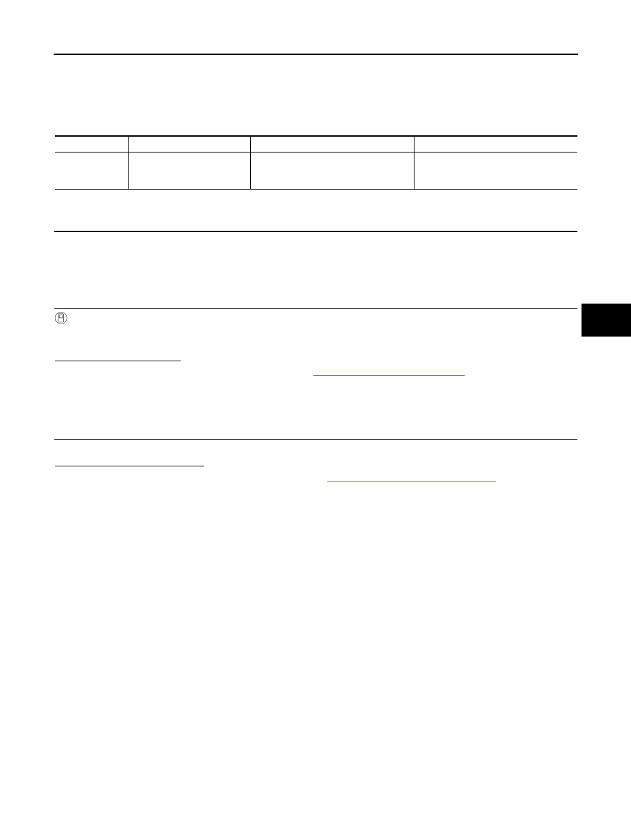
DTC
Display item
Malfunction detected condition
Possible cause
U1010
CONTROL UNIT(CAN)
When detecting error during the initial di-
agnosis of CAN controller to EPS control
unit.
EPS control unit (steering column as-
sembly)