Qashqai J11. Sonar system - part 5
SN
SONAR CONTROL UNIT
SN-65
< ECU DIAGNOSIS INFORMATION >
[WITH PARKING SPACE MEASUREMENT]
C
D
E
F
G
H
I
J
K
L
M
B
A
O
P
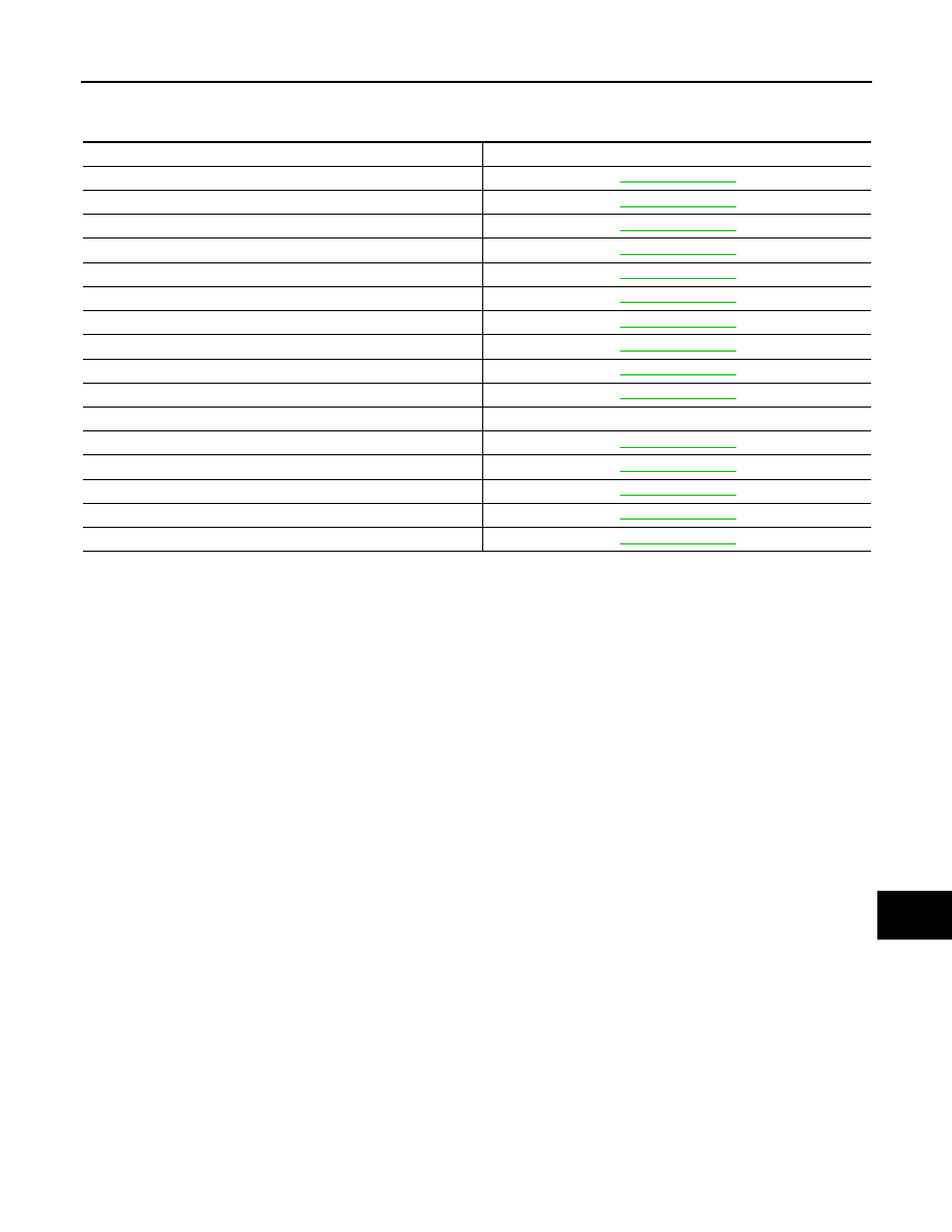
DTC Index
INFOID:0000000010478026
CONSULT Display
Reference Page
U1000: CAN COMM CIRCUIT
U1010: CONTROL UNIT (CAN)
B2710: FRONT LEFT SIDE SPACE MEASUREMENT SENSOR
B2711: FRONT RIGHT SIDE SPACE MEASUREMENT SENSOR
B2720: REAR LEFT SIDE EXTERNAL SENSOR
B2721: REAR LEFT SIDE INTERNAL SENSOR
B2722: REAR RIGHT SIDE INTERNAL SENSOR
B2723: REAR RIGHT SIDE EXTERNAL SENSOR
B2724: ECU
B2725: REAR BUZZER
B2728: LED SWITCH
—
B2729: FRONT LEFT SIDE EXTERNAL SENSOR
B272A: FRONT LEFT SIDE INTERNAL SENSOR
B272B: FRONT RIGHT SIDE INTERNAL SENSOR
B272C: FRONT RIGHT SIDE EXTERNAL SENSOR
B272D: FRONT BUZZER