Qashqai J11. Power window control system - part 2
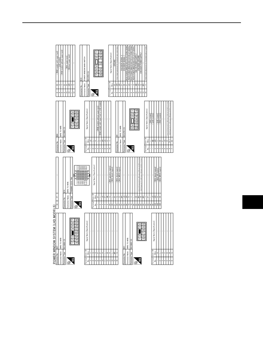
POWER WINDOW SYSTEM
PWC-17
< WIRING DIAGRAM >
C
D
E
F
G
H
I
J
L
M
A
B
PWC
N
O
P
JRKWE4033GB
|
|
|
POWER WINDOW SYSTEM PWC-17 < WIRING DIAGRAM > C D E F G H I J L M A B PWC N O P JRKWE4033GB |