Qashqai J11. Heater & Air conditioning Control System - part 16
COMPONENT PARTS
HAC-241
< SYSTEM DESCRIPTION >
[MANUAL HEATER ]
C
D
E
F
G
H
J
K
L
M
A
B
HAC
N
O
P
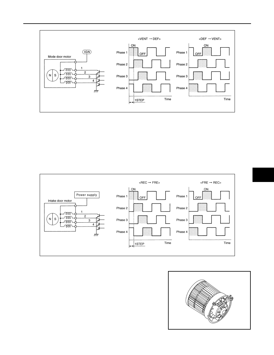
• Direction of rotation is changeable by recomposing pattern of excitation.
A/C UNIT ASSEMBLY : Intake Door Motor
INFOID:0000000010499404
DESCRIPTION
• The step motor system is adopted for intake door motor.
• When a drive signal is input from A/C amp. to door motor, a step motor built into the door motor rotates
according to the drive signal, and then stops at the target door position.
• Rotation of motor is transmitted to intake door by lever, then air inlet is switched.
INTAKE DOOR MOTOR (DRIVER SIDE) DRIVE METHOD
• The 4 drive coils are excited in sequence in order to drive the motor.
• Direction of rotation is changeable by recomposing pattern of excitation.
A/C UNIT ASSEMBLY : Blower Motor
INFOID:0000000010499405
• Brush motor, that rotates coil while brush functions as contact
points, is adopted for blower motor.
• Rotation speed changes according to voltage from power transis-
tor.
JZIIA0033GB
JMIIA3565GB
JMIIA3336ZZ