Qashqai J11. Heater & Air conditioning System - part 2
SYSTEM
HA-17
< SYSTEM DESCRIPTION >
[TYPE 1]
C
D
E
F
G
H
J
K
L
M
A
B
HA
N
O
P
SYSTEM
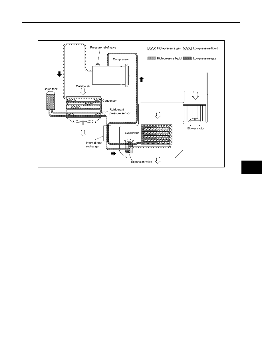
System Diagram
INFOID:0000000010451964
System Description
INFOID:0000000010451965
REFRIGERANT CYCLE
Refrigerant Flow
The refrigerant from the compressor, flows the condenser with liquid tank, the evaporator, and returns to the
compressor. The refrigerant evaporation in the evaporator is controlled by an expansion valve.
Freeze Protection
When intake sensor detects that evaporator surface temperature is 2
°
C (36
°
F) or less, A/C auto amp. (Auto-
matic air conditioning) or A/C amp. (Manual air conditioning) requests ECM to turn the compressor OFF, and
ECM makes A/C relay to OFF, and stops the compressor.
REFRIGERANT SYSTEM PROTECTION
Refrigerant Pressure Sensor
• The refrigerant system is protected against excessively high- or low-pressures by the refrigerant pressure
sensor, installed at the high-pressure pipe 1. The refrigerant pressure sensor detects the pressure inside the
refrigerant line and sends the voltage signal to the ECM if the system pressure rises above, or falls below
the specifications.
• ECM turns the A/C relay to OFF and stops the compressor when the high-pressure side detected by refriger-
ant pressure sensor is following conditions;
- Approximately 3,120 kPa (31.2 bar, 31.8 kg/cm
2
, 452 psi) or more (Engine speed is less than 1,500 rpm.)
- Approximately 2,740 kPa (27.4 bar, 27.9 kg/cm
2
, 397 psi) or more (Engine speed is 1,500 rpm or more.)
- Approximately 140 kPa (1.4 bar, 1.4 kg/cm
2
, 20 psi) or less
Pressure Relief Valve
The refrigerant system is also protected by a pressure relief valve, located in the rear head of the compressor.
The release port on the pressure relief valve automatically opens and releases refrigerant into the atmosphere
when the pressure of refrigerant in the system increases to an unusual level [more than 3,800 kPa (38 bar,
38.8 kg/cm
2
, 551 psi)].
JMIIA3115GB