Qashqai J11. Exterior Lighting system - part 5
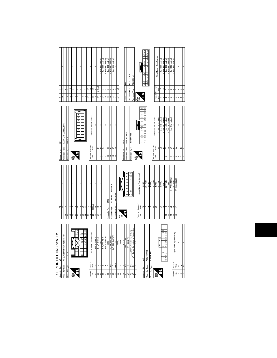
EXTERIOR LIGHTING SYSTEM
EXL-65
< WIRING DIAGRAM >
[LED HEADLAMP]
C
D
E
F
G
H
I
J
K
M
A
B
EXL
N
O
P
JRLWD2228GB
|
|
|
EXTERIOR LIGHTING SYSTEM EXL-65 < WIRING DIAGRAM > [LED HEADLAMP] C D E F G H I J K M A B EXL N O P JRLWD2228GB |