Qashqai J11. Exhaust system (HRA2DDT, K9K, MR20DD) - part 2
PARTICLE FILTER
EX-17
< REMOVAL AND INSTALLATION >
[K9K]
C
D
E
F
G
H
I
J
K
L
M
A
EX
N
P
O
PARTICLE FILTER
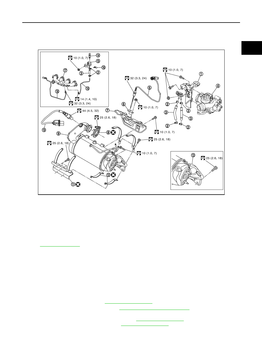
Exploded View
INFOID:0000000010427908
Removal and Installation
INFOID:0000000010427909
CAUTION:
• Be sure to use genuine exhaust system parts or equivalents which are specially designed for heat
resistance, corrosion resistance and shape.
• Perform the operation with the exhaust system fully cooled down because the system is still hot just
after the engine stops.
• Be careful not to cut your hand on the insulator edge.
REMOVAL
1.
Remove exhaust front tube. Refer to
.
2.
Remove front suspension member. Refer to
FSU-21, "Removal and Installation"
3.
Unclip and move aside:
• exhaust gas temperature sensor harness. Refer to
.
• DPF temperature sensor harness. Refer to
1.
DPF pressure sensor bracket
2.
Clamp
3.
Hose
4.
Turbocharger
5.
DPF temperature sensor
6.
Gasket
7.
DPF heat insulator
8.
V-band clamp
9.
Diesel Particle Filter
10. DPF oxygen sensor
11. DPF Bracket
12. DPF bracket strip
13. DPF exhaust gas exit
14. Exhaust gas pressure sensor
15. Exhaust gas pressure sensor bracket
16. Lock plate
17. Exhaust manifold
18. Exhaust gas temperature sensor
19. Exhaust gas pressure sensor tube
E1BIA0896GB