Qashqai J11. Engine mechanical (HRA2DDT, K9K, MR20DD) - part 8


  Index      Nissan     Qashqai J11. Engine mechanical (HRA2DDT, K9K, MR20DD). Service and Repair Manual


Search            copyright infringement  


Content      ..     6      7      8      9     ..


Qashqai J11. Engine mechanical (HRA2DDT, K9K, MR20DD) - part 8


HOW TO SELECT PISTON AND BEARING

EM-113

< UNIT DISASSEMBLY AND ASSEMBLY >

[HRA2DDT]

C

D

E

F

G

H

I

J

K

L

M

A

EM

N

P

O

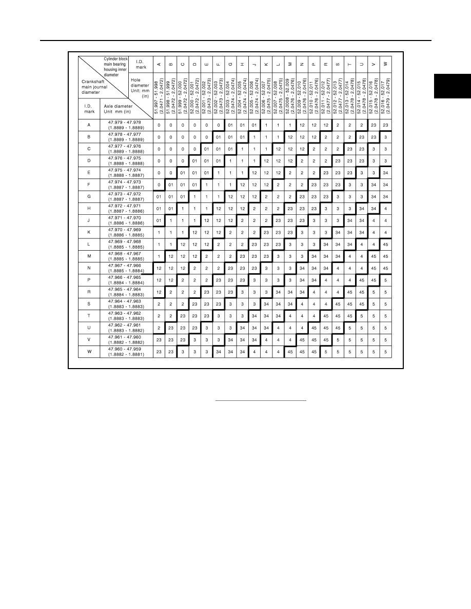
Main Bearing Selection Table 

Main Bearing Grade Table 

E1BIA1172GB

Main Bearing Grade Table

: Refer to 

EM-121, "Main Bearing"

 .

EM-114

< SERVICE DATA AND SPECIFICATIONS (SDS) 

[HRA2DDT]

SERVICE DATA AND SPECIFICATIONS (SDS)

SERVICE DATA AND SPECIFICATIONS (SDS)

SERVICE DATA AND SPECIFICATIONS (SDS)

General Specification

INFOID:0000000010282256

GENERAL SPECIFICATIONS

Drive Belts

INFOID:0000000010282257

Spark Plug

INFOID:0000000010282258

SPARK PLUG (PLATINUM-TIPPED TYPE)

Unit: mm (in)

Camshaft

INFOID:0000000010282260

CAMSHAFT

Unit: mm (in)

Engine type

HRA2DDT

Cylinder arrangement

In-line 4

Displacement

cm

3

 (cu in)

1,197 (73.04)

Bore and stroke

mm (in)

72.2 x 73.1 (2.843 x 2.878)

Valve arrangement

DOHC

Firing order

1-3-4-2

Number of piston rings

Compression

2

Oil

1

Number of main bearings

5

Compression ratio

10.1

Tension of drive belt

Auto adjustment by auto-tensioner

Make

NGK

Standard type

ILKAR7F7G

Gap (Nominal)

0.65 (0.026)

Items

Standard

Limit

Camshaft runout

Intake

No.1

0.01(0.0004)

No.2 to 5

0.015 (0.0006)

Exhaust

No.1

0.01(0.0004)

No.2 to 6

0.015 (0.0006)

SEM671

SERVICE DATA AND SPECIFICATIONS (SDS)

EM-115

< SERVICE DATA AND SPECIFICATIONS (SDS) 

[HRA2DDT]

C

D

E

F

G

H

I

J

K

L

M

A

EM

N

P

O

*: Total indicator reading

VALVE LIFTER

Unit: mm (in)

VALVE CLEARANCE

Unit: mm (in)

*: Approximately 80

°

C (176

°

F)

AVAILABLE VALVE LIFTER

Camshaft cam height “A”

Intake

44.322 - 44.522 (1.7450 - 1.7528)

Exhaust

43.664 - 43.864 (1.7191 - 1.7269)

Camshaft journal diameter

Intake

No.1

27.934 - 28 (1.0998 - 1.1024)

Intake

No.2 to 5

24.969 - 25 (0.9830 - 0.9843)

Camshaft journal diameter

Exhaust

No.1

27.934 - 28 (1.0998 - 1.1024)

Exhaust

No.2 to 6

24.969 - 25 (0.9830 - 0.9843)

Camshaft bracket inner diameter

No. 1

28.044 - 28.076 (1.1041 - 1.1054)

No. 2, 3, 4, 5,6

25.040 - 25.060 (0.9858 - 0.9866)

Camshaft journal oil clearance

Intake

No.1

0.044 - 0.142 (0.0017 - 0.0056)

Intake

No.2 to 5

0.040 - 0.091 (0.0016 - 0.0036)

Camshaft journal oil clearance

Exhaust

No.1

0.044 - 0.142 (0.0017 - 0.0056)

Exhaust

No.2 to 6

0.040 - 0.091 (0.0016 - 0.0036)

Camshaft end play

0.203 - 0.239 (0.008 - 0.0094)

Camshaft radial play

No. 1

0.06 - 0.146 (0.002 - 0.0057)

No. 2, 3, 4, 5,6

0.05 - 0.09 (0.0020 - 0.0035)

Items

Standard

Limit

Items

Standard

Valve lifter outer diameter

29.964 - 29.987 (1.1797 - 1.1806)

Valve lifter hole diameter

30.000 - 30.021 (1.1811 - 1.1819)

Valve lifter clearance

0.013 - 0.057 (0.0005 - 0.0022)

Items

Cold

Intake

0.25 - 0.35 (0.0098 - 0.0138)

Exhaust

0.46 - 0.54 (0.0181 - 0.0213)

Thickness

mm (in)

Identification mark

2.96 (0.1165)

296

2.98 (0.1173)

298

3.00 (0.1181)

300

3.02 (0.1189)

302

KBIA0119E

EM-116

< SERVICE DATA AND SPECIFICATIONS (SDS) 

[HRA2DDT]

SERVICE DATA AND SPECIFICATIONS (SDS)

Cylinder Head

INFOID:0000000010282261

CYLINDER HEAD

Unit: mm (in)

VALVE DIMENSIONS

3.04 (0.1197)

304

3.06 (0.1205)

306

3.08 (0.1213)

308

3.10 (0.1220)

310

3.12 (0.1228)

312

3.14 (0.1236)

314

3.16 (0.1244)

316

3.18 (0.1252)

318

3.20 (0.1260)

320

3.22 (0.1268)

322

3.24 (0.1276)

324

3.26 (0.1283)

326

3.28 (0.1291)

328

3.30 (0.1299)

330

3.32 (0.1307)

332

3.34 (0.1315)

334

3.36 (0.1323)

336

3.38 (0.1331)

338

3.40 (0.1339)

340

3.42 (0.1346)

342

3.44 (0.1354)

344

3.46 (0.1362)

346

3.48 (0.1370)

348

3.50 (0.1378)

350

3.52 (0.1386)

352

3.54 (0.1393)

354

3.56 (0.1402)

356

Thickness

mm (in)

Identification mark

Items

Standard

Limit

Head surface distortion

0.1 (0.004)

Normal cylinder head height “H”

124.8 (4.9134)

PBIC0924E

SERVICE DATA AND SPECIFICATIONS (SDS)

EM-117

< SERVICE DATA AND SPECIFICATIONS (SDS) 

[HRA2DDT]

C

D

E

F

G

H

I

J

K

L

M

A

EM

N

P

O

Unit: mm (in)

VALVE GUIDE

Unit: mm (in)

VALVE SPRING

Unit: mm (in)

Valve head diameter “D”

Intake

26.48 - 26.72 (1.0425 - 1.0520)

Exhaust

23.38 - 23.62 (0.9205 - 0.9299)

Valve length “a”

Intake

100.84 (3.9701)

Exhaust

101.69 (4.0035)

“b”

Intake

1.15 (0.0453)

Exhaust

1.42 (0.0559)

Valve stem diameter “d ”

Intake

5.4705 - 5.4855 (0.2154 - 0.2160)

Exhaust

5.455 - 5.470 (0.2148 - 0.2154)

PBIC3878E

Items

Standard

Valve guide

Inner diameter 

4.8 - 5.0 (0.1890 - 0.1969)

Valve guide clearance

Intake 

0.015 - 0.047 (0.0006 - 0.0019)

Exhaust

0.03 - 0.063 (0.0012 - 0.0025)

PBIC2187E

Items

Standard

Mark on the outer diame-
ter of the springt

Intake Green

Exhaust

Yellow

Internal diameter

17.6 - 18.0 (0.6929 - 0.7087)

Wire diameter

Intake 

2.78 - 2.82 (0.1094 - 0.1110)

Exhaust

2.58 - 2.62 (0.1016 - 0.1031)

Outer diameter

Intake 

23.2 - 23.6 (0.9134 - 0.9291)

Exhaust

22.8 - 23.2 (0.8976 - 0.9134)

EM-118

< SERVICE DATA AND SPECIFICATIONS (SDS) 

[HRA2DDT]

SERVICE DATA AND SPECIFICATIONS (SDS)

Cylinder Block

INFOID:0000000010282262

CYLINDER BLOCK

Unit: mm (in)

AVAILABLE PISTON

Free height

Intake 

45.0 - 47.0 (1.7717 - 1.8504)

Exhaust

58.5 - 60.5 (2.3031 - 2.3819)

Height during control

Intake 32.90 

(1.2953)

Exhaust

24.40 (0.9606)

Load during control

Intake 

138 - 152 N (14.0 - 15.5 kg, 31 - 34 lb)

Exhaust

277 - 303 N (28.2 - 30.9 kg, 62 - 68 lb)

Items

Limit

Valve spring squareness

Intake 

1.4 mm (0.055 in)

Exhaust

1.8 mm (0.071 in)

Cylinder block top surface distortion

Limit

0.1 (0.004)

Cylinder bore inner diameter

Standard

78.000 - 78.015 (3.0709 - 3.0715)

Out-of-round

Limit

0.015 (0.0006)

Taper

0.010 (0.0004)

Cylinder block main bearing housing inner diameter grade

Grade No. A
Grade No. B
Grade No. C
Grade No. D
Grade No. E
Grade No. F
Grade No. G
Grade No. H
Grade No. J
Grade No. K
Grade No. L
Grade No. M
Grade No. N
Grade No. P
Grade No. R
Grade No. S
Grade No. T
Grade No. U
Grade No. V
Grade No. W

51.997 - 51.998 (2.0471 - 2.0472)
51.998 - 51.999 (2.0472 - 2.0472)
51.999 - 52.000 (2.0472 - 2.0472)
52.000 - 52.001 (2.0472 - 2.0473)
52.001 - 52.002 (2.0473 - 2.0473)
52.002 - 52.003 (2.0473 - 2.0474)
52.003 - 52.004 (2.0474 - 2.0474)
52.004 - 52.005 (2.0474 - 2.0474)
52.005 - 52.006 (2.0474 - 2.0475)
52.006 - 52.007 (2.0475 - 2.0475)
52.007 - 52.008 (2.0475 - 2.0476)
52.008 - 52.009 (2.0476 - 2.0476)
52.009 - 52.010 (2.0476 - 2.0476)

52.010 - 52.011 (2.0476 - 2.0477)
52.011 - 52.012 (2.0477 - 2.0477)

52.012 - 52.013 (2.0477 - 2.0478)
52.013 - 52.014 (2.0478 - 2.0478)
52.014 - 52.015 (2.0478 - 2.0478)
52.015 - 52.016 (2.0478 - 2.0479)
52.016 - 52.017 (2.0479 - 2.0479)

Difference in inner diameter between cylinders

Standard

Less than 0.03 (0.0012)

JPBIA2059ZZ

SERVICE DATA AND SPECIFICATIONS (SDS)

EM-119

< SERVICE DATA AND SPECIFICATIONS (SDS) 

[HRA2DDT]

C

D

E

F

G

H

I

J

K

L

M

A

EM

N

P

O

Unit: mm (in)

PISTON RING

Unit: mm (in)

PISTON PIN

Unit: mm (in)

CONNECTING ROD

Unit: mm (in)

CRANKSHAFT

Item

Standard

Limit

Piston skirt diameter “A”

72.15 - 72.17 (2.8405 - 2.8413)

Piston pin hole diameter 

19.996 - 20.002 (0.7872 - 0.7875

Piston to cylinder bore clearance

0.030 - 0.050 (0.0012 - 0.0020)

PBIC0188E

Items

Standard

Limit

Piston ring side clearance

Top

0.030 - 0.070 (0.0012  - 0.0028)

2nd

0.030 - 0.050 (0.0012 - 0.0020)


Oil (rail ring)

0.030 (0.0012)

Piston ring end gap

Top

0.15- 0.30 (0.0059 - 0.0118)

2nd

0.40 - 0.60 (0.0157 - 0.0236)

Oil (rail ring)

0.20 - 0.90 (0.0079 - 0.0354)

Piston pin outer diameter

19.987 - 19.992 (0.7869 - 0.7871)

Piston to piston pin oil clearance

Standard

0.010 - 0.015 (0.0004 - 0.0006)

Connecting rod small end inner diameter

Standard

20.000 - 20.012 (0.7474 - 0.7879)

Connecting rod big end diameter

Grade No. A
Grade No. B
Grade No. C
Grade No. D
Grade No. E
Grade No. F
Grade No. G
Grade No. H
Grade No. J
Grade No. K
Grade No. L
Grade No. M
Grade No. N

45.677 - 45.678 (1.7983 - 1.7987)
45.678 - 45.679 (1.7987 - 1.7984)
45.679 - 45.680 (1.7984 - 1.7984)
45.680 - 45.681 (1.7984 - 1.7985)
45.681 - 45.682 (1.7985 - 1.7985)
45.682 - 45.683 (1.7985 - 1.7985)
45.683 - 45.684 (1.7985 - 1.7986)
45.684 - 45.685 (1.7986 - 1.7986)
45.685 - 45.686 (1.7986 - 1.7987)
45.686 - 45.687 (1.7987 - 1.7987)
45.687 - 45.688 (1.7987 - 1.7987)
45.688 - 45.689 (1.7987 - 1.7988)
45.689 - 45.690 (1.7988 - 1.7988)

EM-120

< SERVICE DATA AND SPECIFICATIONS (SDS) 

[HRA2DDT]

SERVICE DATA AND SPECIFICATIONS (SDS)

Unit: mm (in)

*: Total indicator reading

Crankshaft lateral clearance

0.098 - 0.3 (0.0039 - 0.0118)

Out-of-round

Limit

0.003 (0.0001)

Taper

Limit

0.004 (0.0002)

Runout [TIR*]

Limit

0.02 (0.0008)

Crankshaft end play

Standard

0.098 - 0.260 (0.0039 - 0.0102)

Crankshaft pin journal diameter grade. “Dp”

Grade No. A
Grade No. B
Grade No. C
Grade No. D
Grade No. E
Grade No. F
Grade No. G
Grade No. H
Grade No. J
Grade No. K
Grade No. L
Grade No. M
Grade No. N
Grade No. P
Grade No. R
Grade No. S
Grade No. T
Grade No. U
Grade No. V
Grade No. W

42.009 - 42.010 (1.6539 - 1.6539)
42.008 - 42.009 (1.6539 - 1.6539)
42.007 - 42.008 (1.6538 - 1.6539)
42.006 - 42.007 (1.6538 - 1.6538)
42.005 - 42.006 (1.6538 - 1.6538)
42.004 - 42.005 (1.6537 - 1.6537)
42.003 - 42.004 (1.6537 - 1.6537)
42.002 - 42.003 (1.6536 - 1.6537)
42.001 - 42.002 (1.6536 - 1.6536)
42.000 - 42.001 (1.6535 - 1.6536)
41.999 - 42.000 (1.6535 - 1.6535)
41.998 - 41.999 (1.6535 - 1.6535)
41.997 - 41.998 (1.6534 - 1.6535)
41.996 - 41.997 (1.6534 - 1.6534)
41.995 - 41.996 (1.6533 - 1.6534)
41.994 - 41.995 (1.6533 - 1.6533)
41.993 - 41.994 (1.6533 - 1.6533)
41.992 - 41.993 (1.6532 - 1.6533)
41.991 - 41.992 (1.6531 - 1.6532)
41.990 - 41.991 (1.6531 - 1.6531)

Crankshaft main journal diameter grade. “Dm”

Grade No. A
Grade No. B
Grade No. C
Grade No. D
Grade No. E
Grade No. F
Grade No. G
Grade No. H
Grade No. J
Grade No. K
Grade No. L
Grade No. M
Grade No. N
Grade No. P
Grade No. R
Grade No. S
Grade No. T
Grade No. U
Grade No. V
Grade No. W

47.979 - 47.978 (1.8889 - 1.8889)
47.978 - 47.977 (1.8889 - 1.8889)
47.977 - 47.976 (1.8889 - 1.8888)
47.976 - 47.975 (1.8888 - 1.8888)
47.975 - 47.974 (1.8888 - 1.8887)
47.974 - 47.973 (1.8887 - 1.8887)
47.973 - 47.972 (1.8887 - 1.8887)
47.972 - 47.971 (1.8887 - 1.8886)
47.971 - 47.970 (1.8886 - 1.8886)
47.970 - 47.969 (1.8886 - 1.8885)
47.969 - 47.968 (1.8885 - 1.8885)
47.968 - 47.967 (1.8885 - 1.8885)
47.967 - 47.966 (1.8885 - 1.8884)
47.966 - 47.965 (1.8884 - 1.8884)
47.995 - 47.964 (1.8884 - 1.8883)
47.994 - 47.963 (1.8883 - 1.8883)
47.963 - 47.962 (1.8883 - 1.8883)
47.962 - 47.961 (1.8883 - 1.8882)
47.961 - 47.960 (1.8882 - 1.8882)
47.960 - 47.959 (1.8882 - 1.8881)

SEM645

PBIC3459J

SERVICE DATA AND SPECIFICATIONS (SDS)

EM-121

< SERVICE DATA AND SPECIFICATIONS (SDS) 

[HRA2DDT]

C

D

E

F

G

H

I

J

K

L

M

A

EM

N

P

O

Connecting Rod Bearing

INFOID:0000000010282263

CONNECTING ROD BEARING GRADE TABLE

Unit: mm (in)

Main Bearing

INFOID:0000000010282264

MAIN BEARING GRADE TABLE

Unit: mm (in)

Grade number

Thickness 

Identification color

Remarks

0

1.815 - 1.818 (0.0715 - 0.0716)

Yellow

Grade and color are the same 
for upper and lower bearings.

1

1.818 - 1.821 (0.0716 - 0.0717)

Black

2

1.821 - 1.824 (0.0717 - 0.0718)

Blue

3

1.824 - 1.827 (0.0718 - 0.0719)

Red

4

1.827 - 1.830 (0.0719 - 0.0720)

Green

01

UPR

1.815 - 1.818 (0.0715 - 0.0716)

Yellow

Grade and color are different 
for upper and lower bearings.

LWR

1.818 - 1.821 (0.0716 - 0.0717)

Black

12

UPR

1.818 - 1.821 (0.0716 - 0.0717)

Black

LWR

1.821 - 1.824 (0.0717 - 0.0718)

Blue

23

UPR

1.821 - 1.824 (0.0717 - 0.0718)

Blue

LWR

1.824 - 1.827 (0.0718 - 0.0719)

Red

34

UPR

1.824 - 1.827 (0.0718 - 0.0719)

Red

LWR

1.827 - 1.830 (0.0719 - 0.0720)

Green

Grade number

Thickness 

Identification color

Remarks

0

2.0000 - 2.0015 (0.0787 - 0.0788)

Black

Grade and color are the same 
for upper and lower bearings.

1

2.0030 - 2.0045 (0.0789 - 0.0789)

White

2

2.0060 - 2.0075 (0.0790 - 0.0790)

Green

3

2.0090 - 2.0105 (0.0791 - 0.0792)

Yellow

4

2.0120 - 2.0135 (0.0792 - 0.0793)

Blue

5

2.0150 - 2.0165 (0.0793 - 0.0794)

Red

SEM685D

EM-122

< SERVICE DATA AND SPECIFICATIONS (SDS) 

[HRA2DDT]

SERVICE DATA AND SPECIFICATIONS (SDS)

01

UPR

2.0000 - 2.0015 (0.0787 - 0.0788)

Black

Grade and color are different 
for upper and lower bearings.

LWR

2.0030 - 2.0045 (0.0789 - 0.0789)

White

12

UPR

2.0030 - 2.0045 (0.0789 - 0.0789)

White 

LWR

2.0060 - 2.0075 (0.0790 - 0.0790)

Green

23

UPR

2.0060 - 2.0075 (0.0790 - 0.0790)

Green 

LWR

2.0090 - 2.0105 (0.0791 - 0.0792)

Yellow

34

UPR

2.0090 - 2.0105 (0.0791 - 0.0792)

Yellow

LWR

2.0120 - 2.0135 (0.0792 - 0.0793)

Blue

45

UPR

2.0120 - 2.0135 (0.0792 - 0.0793)

Blue

LWR

2.0150 - 2.0165 (0.0793 - 0.0794)

Red

Grade number

Thickness 

Identification color

Remarks

SEM685D

PRECAUTIONS

EM-123

< PRECAUTION >

[MR20DD]

C

D

E

F

G

H

I

J

K

L

M

A

EM

N

P

O

PRECAUTION

PRECAUTIONS

Precaution for Supplemental Restraint System (SRS) "AIR BAG" and "SEAT BELT 
PRE-TENSIONER"

INFOID:0000000010715440

The Supplemental Restraint System such as “AIR BAG” and “SEAT BELT PRE-TENSIONER”, used along
with a front seat belt, helps to reduce the risk or severity of injury to the driver and front passenger for certain
types of collision. Information necessary to service the system safely is included in the “SRS AIR BAG” and
“SEAT BELT” of this Service Manual.

WARNING:

Always observe the following items for preventing accidental activation.
• To avoid rendering the SRS inoperative, which could increase the risk of personal injury or death in

the event of a collision that would result in air bag inflation, all maintenance must be performed by
an authorized NISSAN/INFINITI dealer.

• Improper maintenance, including incorrect removal and installation of the SRS, can lead to personal

injury caused by unintentional activation of the system. For removal of Spiral Cable and Air Bag
Module, see “SRS AIR BAG”.

• Never use electrical test equipment on any circuit related to the SRS unless instructed to in this Ser-

vice Manual. SRS wiring harnesses can be identified by yellow and/or orange harnesses or harness
connectors.

PRECAUTIONS WHEN USING POWER TOOLS (AIR OR ELECTRIC) AND HAMMERS

WARNING:

Always observe the following items for preventing accidental activation.
• When working near the Air Bag Diagnosis Sensor Unit or other Air Bag System sensors with the

ignition ON or engine running, never use air or electric power tools or strike near the sensor(s) with
a hammer. Heavy vibration could activate the sensor(s) and deploy the air bag(s), possibly causing
serious injury.

• When using air or electric power tools or hammers, always switch the ignition OFF, disconnect the

battery, and wait at least 3 minutes before performing any service.

Precaution Necessary for Steering Wheel Rotation After Battery Disconnect

INFOID:0000000010715441

CAUTION:

Comply with the following cautions to prevent any error and malfunction.
• Before removing and installing any control units, first turn the ignition power source and accessory

power source to the OFF, then disconnect both battery cables.

• After finishing work, confirm that all control unit connectors are connected properly, then re-connect

both battery cables.

• Always use CONSULT to perform self-diagnosis as a part of each function inspection after finishing

work. If a DTC is detected, perform trouble diagnosis according to self-diagnosis results.

For vehicle with steering lock unit, if the battery is disconnected or discharged, the steering wheel will lock and
cannot be turned.
If turning the steering wheel is required with the battery disconnected or discharged, follow the operation pro-
cedure below before starting the repair operation.

OPERATION PROCEDURE

1.

Connect both battery cables.
NOTE:
Supply power using jumper cables if battery is discharged.

2.

Open driver door.

3.

Turn the ignition switch to the ON position.
(At this time, the steering lock will be released.)

4.

Turn the ignition switch to OFF position with driver door open.

5.

Wait for 3 minutes or longer with driver door open.
NOTE:
• Do not close driver door because the steering wheel locks when driver door is closed.

EM-124

< PRECAUTION >

[MR20DD]

PRECAUTIONS

• The auto acc function is adapted to this vehicle. For this reason, even when the ignition switch is turned

to OFF position, the accessory power source does not turned OFF and continues to be supplied for a
certain amount of time.

6.

Disconnect both battery cables. The steering lock will remain released with both battery cables discon-
nected and the steering wheel can be turned.

7.

Perform the necessary repair operation.

8.

When the repair work is completed, re-connect both battery cables. With the brake pedal released, turn
the ignition switch from OFF position to ON position, then to LOCK position. (The steering wheel will lock
when the ignition switch is turned to LOCK position.)

9.

Perform self-diagnosis check of all control units using CONSULT.

Precaution for Procedure without Cowl Top Cover

INFOID:0000000010715442

When performing the procedure after removing cowl top cover, cover
the lower end of windshield with urethane, etc to prevent damage to
windshield.

Precaution for Handling High Pressure Fuel System

INFOID:0000000010715443

• High pressure fuel system components are between high pressure fuel pump and fuel injector.
• Always release fuel pressure and never start the engine when performing removal and installation.
• When removing or installing parts without releasing fuel pressure, fuel may be splashed and, if fuel contacts

skin or eyes, it may cause inflammation.

Special Cautions to Ensure the Safe Disposal of Sodium-filled Valves

INFOID:0000000010715444

Handling and disposal of sodium-filled valves requires special care
and consideration. Under conditions such as breakage with subse-
quent contact with water, metal sodium which lines the inner portion
of valve will react violently, forming sodium hydroxide and hydrogen
which may result in an explosion. Sodium-filled valve is identified on
the top of its stem as shown in illustration.

DEALER DISPOSAL INSTRUCTIONS

CAUTION:

• Use approved shatter-resistant eye protection when performing this procedure.
• Perform this and all subsequent disposal work procedures in an open room, away from flammable

liquids. Keep a fire extinguisher, rated at least 10 ABC, in close proximity to the work area.

• Be sure to wear rubber gloves when performing the following operations.
• Make sure the resultant (high alkalinity) waste water does not contact your skin. If the waste water

does contact you, wash the contacted area immediately with large quantities of water.

• Dealers should check their respective state and local regulations concerning any chemical treatment

or waste water discharge permits which may be required to dispose of the resultant (high alkalinity)
waste water.

PIIB3706J

Identification mark of sodium-filled valve 

Intake

: 4BA

Exhaust

: 4BB

JPBIA6407ZZ

PRECAUTIONS

EM-125

< PRECAUTION >

[MR20DD]

C

D

E

F

G

H

I

J

K

L

M

A

EM

N

P

O

1.

Clamp valve stem in a vice.

2.

The valve has a specially-hardened surface. To cut through it,
first remove a half-round section, approximately 30 mm (1.18 in)
long using air-powered grinder until black color is removed and
silver color appears.

3.

Use hacksaw to cut through approximately half the diameter of
valve stem. Make the serration at a point 40 mm (1.57 in) from
the end of valve stem.

4.

Cover the serrated end of the valve with a large shop towel (A).
Strike the valve face end with a hammer, separating it into two
pieces.

5.

Fill a bucket (such as a 20   oil can) with at least 10   (2-1/4
lmp gal) of water. Carefully place the already cut (serrated)
valves into the water one-at-a-time using a set of large tweezers
and quickly move away at least 2.7 m (9 ft).

6.

The valves should be placed in a standing position as shown in
the illustration to allow complete reaction. After the bubbling
action has subsided, additional valves can be placed into the
bucket allowing each subsequent chemical reaction to subside.
However, no more than 8 valves should be placed in the same
10   (2-1/4 lmp gal) amount of water. The complete chemical
reaction may take as long as 4 to 5 hours. Remove the valves
using a set of large tweezers after the chemical reaction has
stopped. Afterwards, valves can be disposed as ordinary scrap.

Precautions For Engine Service

INFOID:0000000010715445

DISCONNECTING FUEL PIPING

• Before starting work, check no fire or spark producing items are in the work area. 
• Release fuel pressure before disconnecting and disassembly.
• After disconnecting pipes, plug openings to stop fuel leakage.

DRAINING ENGINE COOLANT

Drain engine coolant and engine oil when the engine is cooled.

INSPECTION, REPAIR AND REPLACEMENT

A

:  Black  color

B

:  Silver  color

c

: 47 mm (1.85 in)

d

: 17 mm (0.67 in)

JPBIA4964ZZ

a

: 32 mm (1.26 in)

JPBIA4965ZZ

JPBIA4966ZZ

A

: Bucket (Such as 20 

 oil can)

JPBIA4967ZZ

EM-126

< PRECAUTION >

[MR20DD]

PRECAUTIONS

Before repairing or replacing, thoroughly inspect parts. Inspect new replacement parts in the same way, and
replace if necessary.

REMOVAL AND DISASSEMBLY

• When instructed to use SST, use specified tools. Always be careful to work safely, avoid forceful or unin-

structed operations. 

• Exercise maximum care to avoid damage to mating or sliding surfaces.
• Dowel pins are used for several parts alignment. When replacing and reassembling parts with dowel pins,

check that dowel pins are installed in the original position.

• Must cover openings of engine system with a tape or equivalent, to seal out foreign materials.
• Mark and arrange disassembly parts in an organized way for easy troubleshooting and reassembly.
• When loosening nuts and bolts, as a basic rule, start with the one furthest outside, then the one diagonally

opposite, and so on. If the order of loosening is specified, do exactly as specified. Power tools may be used
in the step.

ASSEMBLY AND INSTALLATION

• Use torque wrench to tighten bolts or nuts to specification.
• When tightening nuts and bolts, as a basic rule, equally tighten in several different steps starting with the

ones in center, then ones on inside and outside diagonally in this order. If the order of tightening is specified,
do exactly as specified.

• Replace with new gasket, packing, oil seal or O-ring.
• Thoroughly wash, clean, and air-blow each part. Carefully check engine oil or engine coolant passages for

any restriction and blockage. 

• Avoid damaging sliding or mating surfaces. Completely remove foreign materials such as cloth lint or dust.

Before assembly, oil sliding surfaces well. 

• After disassembling, or exposing any internal engine parts, change engine oil and replace oil filter with a new

one.

• Release air within route when refilling after draining engine coolant. 
• After repairing, start the engine and increase engine speed to check engine coolant, fuel, engine oil, and

exhaust gases for leakage.

Parts Requiring Angle Tightening

INFOID:0000000010715446

• Use the angle wrench [SST: KV10112100] for the final tightening of the following engine parts: 
- Camshaft sprocket (INT) bolt
- Cylinder head bolts
- Main bearing cap bolts
- Connecting rod cap bolts
- Crankshaft pulley bolt (No the angle wrench is required as bolt flange is provided with notches for angle

tightening)

• Do not use a torque value for final tightening. 
• The torque value for these parts are for a preliminary step.
• Ensure thread and seat surfaces are clean and coated with engine oil. 

Liquid Gasket

INFOID:0000000010715447

REMOVAL OF LIQUID GASKET SEALING

• After removing mounting nuts and bolts, separate the mating sur-

face using the seal cutter [SST: KV10111100] (A) and remove old
liquid gasket sealing.

CAUTION:

Be careful not to damage the mating surfaces.

• Tap the seal cutter [SST: KV10111100] to insert it 

, and then slide

it 

 by tapping on the side as shown in the figure.

• In areas where the seal cutter [SST: KV10111100] is difficult to use,

use a plastic hammer to lightly tap the parts, to remove it.

CAUTION:

If for some unavoidable reason tool such as a screwdriver is
used, be careful not to damage the mating surfaces.

JPBIA0052ZZ

PRECAUTIONS

EM-127

< PRECAUTION >

[MR20DD]

C

D

E

F

G

H

I

J

K

L

M

A

EM

N

P

O

LIQUID GASKET APPLICATION PROCEDURE

1.

Using a scraper (A), remove old liquid gasket adhering to the liq-
uid gasket application surface and the mating surface.
• Remove liquid gasket completely from the groove of the liquid

gasket application surface, mounting bolts, and bolt holes.

2.

Wipe the liquid gasket application surface and the mating sur-
face with white gasoline (lighting and heating use) to remove
adhering moisture, grease and foreign materials.

3.

Attach liquid gasket tube to the tube presser (commercial ser-
vice tool).
Use Genuine Liquid Gasket or equivalent.

4.

Apply liquid gasket without breaks to the specified location with
the specified dimensions.
• If there is a groove for liquid gasket application, apply liquid

gasket to the groove.

• As for bolt holes 

, normally apply liquid gasket inside the

holes. Occasionally, it should be applied outside the holes.
Check to read the text of this manual.

• Within five minutes of liquid gasket application, install the mat-

ing component.

• If liquid gasket protrudes, wipe it off immediately.
• Do not retighten mounting bolts or nuts after the installation.
• After 30 minutes or more have passed from the installation, fill

engine oil and engine coolant.

CAUTION:

If there are specific instructions in this manual, observe them.

Precautions for Removing Battery Terminal

INFOID:0000000010715448

• With the adoption of Auto ACC function, ACC power is automatically supplied by operating the intelligent key

or remote keyless entry or by opening/closing the driver side door. In addition, ACC power is supplied even
after the ignition switch is turned to the OFF position, i.e. ACC power is supplied for a certain fixed time.

• When disconnecting the 12V battery terminal, turn off the ACC

power before disconnecting the 12V battery terminal, observing
“How to disconnect 12V battery terminal” described below.
NOTE:
Some ECUs operate for a certain fixed time even after ignition
switch is turned OFF and ignition power supply is stopped. If the
battery terminal is disconnected before ECU stops, accidental DTC
detection or ECU data damage may occur.

•  For vehicles with the 2-batteries, be sure to connect the main bat-

tery and the sub battery before turning ON the ignition switch.
NOTE:
If the ignition switch is turned ON with any one of the terminals of
main battery and sub battery disconnected, then DTC may be detected.

•  After installing the 12V battery, always check "Self Diagnosis Result" of all ECUs and erase DTC.

JPBIA0053ZZ

EMA0622D

: Groove

: Inside

JPBIA0010ZZ

SEF289H

EM-128

< PRECAUTION >

[MR20DD]

PRECAUTIONS

NOTE:
The removal of 12V battery may cause a DTC detection error.

HOW TO DISCONNECT 12V BATTERY TERMINAL

Disconnect 12V battery terminal according to Instruction 1 or Instruction 2 described below.
For vehicles parked by ignition switch OFF, refer to Instruction 2.

INSTRUCTION 1

1.

Open the hood.

2.

Turn key switch to the OFF position with the driver side door opened.

3.

Get out of the vehicle and close the driver side door.

4.

Wait at least 3 minutes. 

CAUTION:

While waiting, never operate the vehicle such as locking, opening, and closing doors. Violation of
this caution results in the activation of ACC power supply according to the Auto ACC function.

5.

Remove 12V battery terminal.

CAUTION:

After installing 12V battery, always check self-diagnosis results of all ECUs and erase DTC.

INSTRUCTION 2 (FOR VEHICLES PARKED BY IGNITION SWITCH OFF)

1.

Unlock the door with intelligent key or remote keyless entry.
NOTE:
At this moment, ACC power is supplied.

2.

Open the driver side door.

3.

Open the hood.

4.

Close the driver side door.

5.

Wait at least 3 minutes. 

CAUTION:

While waiting, never operate the vehicle such as locking, opening, and closing doors. Violation of
this caution results in the activation of ACC power supply according to the Auto ACC function.

6.

Remove 12V battery terminal.

CAUTION:

After installing 12V battery, always check self-diagnosis results of all ECUs and erase DTC.


Content      ..     6      7      8      9     ..