Qashqai J11. Engine control system (MR20DD) - part 6
ECM-82
< ECU DIAGNOSIS INFORMATION >
[MR20DD]
ECM
51
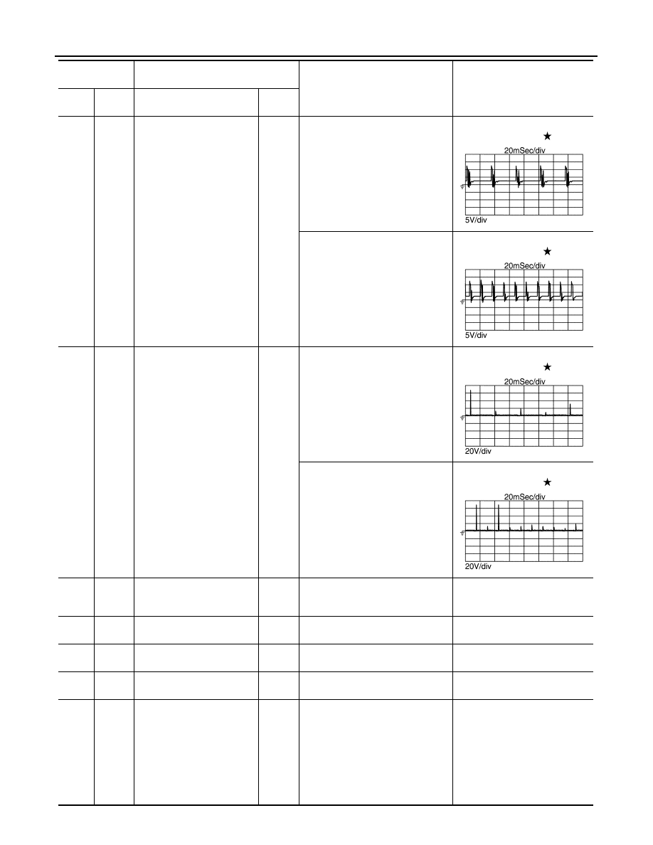
(W)
54
(B)
High pressure fuel pump (HI)
Output
[Engine is running]
• Engine: after warming up
• Idle speed
NOTE:
The pulse cycle changes depend-
ing on rpm at idle.
BATTERY VOLTAGE
(11 – 14 V)
[Engine is running]
• Engine: after warming up
• Engine speed: 2,000 rpm
BATTERY VOLTAGE
(11 – 14 V)
52
(O)
128
(B)
High pressure fuel pump
(LO)
Output
[Engine is running]
• Engine: after warming up
• Idle speed
NOTE:
The pulse cycle changes depend-
ing on rpm at idle.
BATTERY VOLTAGE
(11 – 14 V)
[Engine is running]
• Engine: after warming up
• Engine speed: 2,000 rpm
BATTERY VOLTAGE
(11 – 14 V)
53
(W)
55
(GR)
Fuel injector driver power
supply 2
Input
[Engine is running]
• Engine: after warming up
• Idle speed
BATTERY VOLTAGE
(11 – 14 V)
54
(B)
—
ECM ground (High pressure
fuel pump)
—
—
—
55
(GR)
—
ECM ground (Fuel injector)
—
—
—
56
(V)
—
ECM ground (Fuel injector)
—
—
—
57
(Y)
59
(B)
Heated oxygen sensor 2
Input
[Engine is running]
• Revving engine from idle to 3,000
rpm quickly after the following
conditions are met
- Engine: after warming up
- Keeping the engine speed be-
tween 3,500 and 4,000 rpm for 1
minute and at idle for 1 minute un-
der no load
0 – 1.0 V
Terminal No.
(Wire color)
Description
Condition
Value
(Approx.)
+
−
Signal name
Input/
Output
JPBIA4722ZZ
JPBIA4723ZZ
JPBIA4724ZZ
JPBIA4725ZZ