Qashqai J11. Engine control system (HRA2DDT) - part 2


  Index      Nissan     Qashqai J11. Engine control system (HRA2DDT). Service and Repair Manual


Search            copyright infringement  


Content      ..      1      2      3      ..


Qashqai J11. Engine control system (HRA2DDT) - part 2


COMPONENT PARTS

ECH-17

< SYSTEM DESCRIPTION >

[HRA2DDT]

C

D

E

F

G

H

I

J

K

L

M

A

ECH

N

P

O

feedback to the ECM, when opens/closes the throttle valve in response to driving conditions via the throttle
control motor.

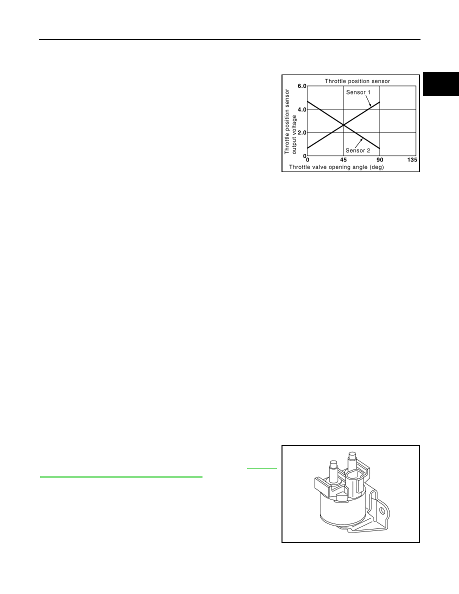
THROTTLE POSITION SENSOR

The throttle position sensor responds to the throttle valve movement.
The throttle position sensor has two sensors. These sensors are a
kind of potentiometer which transform the throttle valve position into
output voltage, and emit the voltage signal to the ECM. The ECM
judges the current opening angle of the throttle valve from these sig-
nals and controls the throttle valve opening angle in response to
driving conditions via the throttle control motor.

Engine Coolant Bypass Valve

INFOID:0000000010471168

Engine Coolant Bypass Valve switches the flow passage of engine coolant. This valve is controlled by Engine
Coolant Bypass Valve Control Solenoid Valve.

Engine Coolant Bypass Valve Control Solenoid Valve

INFOID:0000000010471169

Engine coolant bypass valve control solenoid valve is controlled by ECM. The solenoid valve controls negative
pressure given to diaphragm of engine coolant bypass valve. When engine coolant bypass valve control sole-
noid valve is activated, it opens solenoid valve and gives negative pressure from vacuum pump to diaphragm
of engine coolant bypass valve.

Engine Coolant Temperature Sensor

INFOID:0000000010379011

The engine coolant temperature sensor is used to detect the engine coolant temperature. The sensor modifies
a voltage signal from the ECM. The modified signal returns to the ECM as the engine coolant temperature
input.

Engine Oil Pressure Control Solenoid Valve

INFOID:0000000010471166

The engine oil pressure control solenoid valve regulates the engine oil pressure.

Engine Restart Relay

INFOID:0000000010471138

The engine restart relay is controlled by ECM when restarting the engine during the stop/start system opera-
tion.

Engine Restart Bypass Control Relay

INFOID:0000000010471139

The engine restart bypass control relay is controlled by ECM and controls the engine restart bypass relay.

Engine Restart Bypass Relay

INFOID:0000000010471140

The engine restart bypass relay reduces battery voltage drop right
after the starter motor activation at an engine restart by switching the
electric circuit of the starter motor. For details, refer to 

ECH-33,

"STOP/START SYSTEM : System Description"

.

PBIB0145E

JSBIA1994ZZ

ECH-18

< SYSTEM DESCRIPTION >

[HRA2DDT]

COMPONENT PARTS

EVAP Canister Purge Volume Control Solenoid Valve

INFOID:0000000010379012

The EVAP canister purge volume control solenoid valve controls the flow rate of fuel vapor from the EVAP
canister.

Exhaust Valve Timing Control Position Sensor

INFOID:0000000010471157

Exhaust valve timing control position sensor detects the protrusion of the signal plate installed to the exhaust
camshaft. 
This sensor signal is used for sensing a position of the exhaust camshaft.

Exhaust Valve Timing Control Solenoid Valve

INFOID:0000000010471149

Exhaust valve timing control solenoid valve is controlled by ECM.

Fuel Injector

INFOID:0000000010379013

For the fuel injector, a high pressure fuel injector is used and this enables a high-pressure fuel injection within
a short time.

Fuel Rail Pressure Sensor

INFOID:0000000010471147

The fuel rail pressure (FRP) sensor is placed to the fuel rail. It measures the fuel pressure in the fuel rail. The
sensor sends voltage signal to the ECM. As the pressure increases, the voltage rises. ECM operates fuel flow
actuator according to feedback signal from fuel rail pressure sensor, and controls fuel pressure inside fuel rail.

Heated Oxygen Sensor 1

INFOID:0000000010379015

DESCRIPTION

The heated oxygen sensor 1 is placed into the exhaust manifold. It detects the amount of oxygen in the
exhaust gas compared to the outside air. The heated oxygen sensor 1 signal is sent to the ECM. The ECM
adjusts the injection pulse duration to achieve the ideal air-fuel ratio.

HEATED OXYGEN SENSOR 1 HEATER

Heated oxygen sensor 1 heater is integrated in the sensor.
The ECM performs ON/OFF control of the heated oxygen sensor 1 heater.

Heated Oxygen Sensor 2

INFOID:0000000010379016

DESCRIPTION

The heated oxygen sensor 2, after three way catalyst (manifold), monitors the oxygen level in the exhaust gas.

HEATED OXYGEN SENSOR 2 HEATER

Heated oxygen sensor 2 heater is integrated in the sensor.
The ECM performs ON/OFF control of the heated oxygen sensor 2 heater.

High Pressure Fuel Pump

INFOID:0000000010471146

High pressure fuel pump pumps fuel to the fuel rail.

Hood Switch

INFOID:0000000010471143

Hood switch is located around radiator core support. Hood switch detects open/close condition of hood and
input the hood switch signal to IPDM E/R.

Ignition Coil

INFOID:0000000010379017

ECM turns ON and OFF the ignition coil primary circuit. This ON/OFF operation induces the proper high volt-
age in the coil secondary circuit.

Intake Air Temperature Sensor

INFOID:0000000010379018

The intake air temperature sensor detects intake air temperature and transmits a signal to the ECM.

COMPONENT PARTS

ECH-19

< SYSTEM DESCRIPTION >

[HRA2DDT]

C

D

E

F

G

H

I

J

K

L

M

A

ECH

N

P

O

Intake Manifold Pressure Sensor

INFOID:0000000010379021

The intake manifold pressure sensor is installed to the intake manifold. Detects intake manifold pressure, and
transmits a voltage signal to the ECM.

Intake Valve Timing Control Solenoid Valve

INFOID:0000000010471150

Intake valve timing control solenoid valve is controlled by ECM.

Knock Sensor

INFOID:0000000010379019

The knock sensor is attached to the cylinder block. It senses engine knocking.

Fuel Pump

INFOID:0000000010379014

Fuel pump is installed in the fuel tank and pumps fuel to the high puressure fuel pump.

Malfunction Indicator Lamp

INFOID:0000000010379020

Malfunction Indicator lamp (MIL) is located on the combination
meter.
MIL will illuminate when the ignition switch is turned ON without the
engine running. This is a bulb check.
When the engine is started, MIL should turn OFF. If the MIL remains
illuminated, the on board diagnostic system has detected an engine
system malfunction.

Reverse/Neutral Position Switch

INFOID:0000000010471177

Reverse/Neutral position switch detects gear position is reverse/neutral.

Refrigerant Pressure Sensor

INFOID:0000000010379022

The refrigerant pressure sensor is installed at the condenser of the air conditioner system. The sensor uses an
electrostatic volume pressure transducer to convert refrigerant pressure to voltage. The voltage signal is sent
to ECM, and ECM controls cooling fan system.

Stop Lamp Switch

INFOID:0000000010379023

Stop lamp switch is installed to brake pedal bracket.
Brake switch signal is applied to the ECM through the stop lamp switch when the brake pedal is depressed.
This signal is used mainly to decrease the engine speed when the vehicle is being driven.

Stop/Start Indicator Lamp

INFOID:0000000010471144

The stop/start indicator lamp is located on the combination meter.
The stop/start indicator lamp turns ON when the stop/start system is
operating.
When a malfunction is detected in the stop/start system, the stop/
start indicator lamp blinks at a slow speed to alert the driver to the
malfunction. When a driver

s operation is judged as dangerous one

during stop/start system operation, the stop/start indicator lamp
blinks at a high speed.

Stop/start indicator lamp status

JPNIA1882ZZ

JPBIA4266ZZ

ECH-20

< SYSTEM DESCRIPTION >

[HRA2DDT]

COMPONENT PARTS

*: Engine is stalled after alert for 1.5 seconds.

Stop/Start OFF Switch

INFOID:0000000010471145

The stop/start OFF switch is mounted on the switch panel of the
driver side lower instrument panel. When the stop/start OFF switch
is pressed, the indicator lump turns ON and the stop/start system
can be deactivated.
For further details, refer to 

ECH-44, "STOP/START SYSTEM :

Switch Name and Function"

.

Thermostat Heater Control Solenoid Valve

INFOID:0000000010471165

The thermostat heater control solenoid valve regulates the coolant temperature within normal operation tem-
perature.

Turbocharger wastegate control solenoid valve

INFOID:0000000010436298

Turbocharger wastegate control solenoid valve actuates the wastegate diaphragm. An output pressure of the
valve is between ambient pressure and boost pressure. When this valve is driven, the wastegate valve closes.

Turbocharger Boost Sensor

INFOID:0000000010436212

Turbocharger boost sensor is used to get the boost pressure information in order to adapt the intake manifold
pressure to the set-point.

Turbocharger bypass valve control solenoid valve

INFOID:0000000010436213

Turbocharger bypass valve control solenoid valve is used to release high pressure air upstream the compres-
sor in order to decrease pressure between the turbocharger outlet and throttle valve. Accordingly, this opera-
tion prevents the decrease in turbine speed and improves the response time of charging when shifting gears.

System condition

Condition

Stop/start indicator lamp

Warning chime

Operate

Normal

Illuminate

Door (driver side) open 
and seat belt released

High speed blinking

Sound

Hood open

High speed blinking

*

Sound

*

Fail-Safe

Starter motor operation 
counter: too much

Slow speed blinking

Malfunction of stop/start 
system

Slow speed blinking

JSBIA4078ZZ

SYSTEM

ECH-21

< SYSTEM DESCRIPTION >

[HRA2DDT]

C

D

E

F

G

H

I

J

K

L

M

A

ECH

N

P

O

SYSTEM

ENGINE CONTROL SYSTEM

ENGINE CONTROL SYSTEM : System Description

INFOID:0000000010379026

SYSTEM DIAGRAM

SYSTEM DESCRIPTION

JSBIA4857GB

ECH-22

< SYSTEM DESCRIPTION >

[HRA2DDT]

SYSTEM

ECM controls the engine by various functions.

ENGINE SPEED CONTROL

ENGINE SPEED CONTROL : System Description

INFOID:0000000010379027

SYSTEM DESCRIPTION

The engine speed control consists of the following functions:
• Cranking and cylinder identification
• Curative anti-jerk
• Idle speed control
• Engine speed limitation
• Engine state

CRANKING AND CYLINDER IDENTIFICATION

ECM controls the engine speed during cranking.
ECM sets and resets fuel injection timing.
ECM decides engine speed in cranking by detections restart status and controls fuel injection quantity.
ECM identifies a cylinder without camshaft sensor.
The aim of this function is to confirm whether the phase is correct.
The gathering composed of five flywheel teeth is stored and measured for every each TDC (top dead center).
The engine speed must be up to around 300 rpm and less than around 5000 rpm.
This function is functional 95% of the time.

CURATIVE ANTI-JERK

This function aims to smooth the engine speed through torque corrections out of idle engine speed regulation.
The torque correction is made by the anti-jerk function to damp the engine speed vibrations caused by the
drive-line vibrations.

IDLE SPEED CONTROL

ECM calculates the engine idle speed set point and maintains the engine speed in order to follow the set point.
The engine idle speed set-point is computed from following load and signal:
• Post treatment

Function

Reference

ENGINE SPEED CONTROL SYSTEM

ECH-22, "ENGINE SPEED CONTROL : System Description"

POWERTRAIN COORDINATION CONTROL

ECH-23, "POWERTRAIN COORDINATION CONTROL : System 
Description"

INTAKE AIR SYSTEM

ECH-24, "INTAKE AIR SYSTEM : System Description"

VARIABLE VALVE TIMING CONTROL

ECH-24, "VARIABLE VALVE TIMING CONTROL : System De-
scription"

TURBOCHARGER BOOST CONTROL

ECH-25, "TURBOCHARGER BOOST CONTROL : System De-
scription"

ENGINE TORQUE CONTROL

ECH-25, "ENGINE TORQUE CONTROL : System Description"

COMBUSTION CONTROL

ECH-27, "COMBUSTION CONTROL : System Description"

AFTER TREATMENT SYSTEM

ECH-31, "AFTER TREATMENT SYSTEM : System Description"

COOLING FAN CONTROL

ECH-31, "COOLING FAN CONTROL : System Description"

THERMOSTAT CONTROL

ECH-31, "THERMOSTAT CONTROL : System Description"

ENERGY MANAGEMENT SYSTEM

ECH-32, "ENERGY MANAGEMENT SYSTEM : System Descrip-
tion"

STOP/START SYSTEM

ECH-33, "STOP/START SYSTEM : System Description"

AUTOMATIC SPEED CONTROL DEVICE (ASCD)

ECH-40, "AUTOMATIC SPEED CONTROL DEVICE (ASCD) : 
System Description"

SPEED LIMITER

ECH-41, "SPEED LIMITER : System Description"

GEAR SHIFT INDICATOR SYSTEM

ECH-42, "GEAR SHIFT INDICATOR SYSTEM : System Descrip-
tion"

CAN COMMUNICATION

ECH-42, "CAN COMMUNICATION : System Description"

SYSTEM

ECH-23

< SYSTEM DESCRIPTION >

[HRA2DDT]

C

D

E

F

G

H

I

J

K

L

M

A

ECH

N

P

O

- Catalyst warm-up
• Electric consumers
- Cooling fan
- Power window
- Air heater (air conditioning system)
- Alternator output current
• Automatic transmission
- Automatic transmission idle speed set point function (according to coolant temperature)
- Automatic transmission idle speed increase request
• Mechanical consumers
- Air conditioning
- Power steering
• Diagnosis and protection
- Diagnosis
- Engine protection by oil temperature survey
- CONSULT function
- Intake manifold pressure sensor signal
The final engine idle speed set point is computed from each consumer

s engine idle speed set point:

• Three correction torques for idle speed regulation are computed:
- Proportional
- Integral
- Derivative
• The final corrective torque of the Idle Speed Regulation is obtained taking into account proportional, integral,

and derivative corrections.

ENGINE SPEED LIMITATION

ECM calculates the maximum engine speed set point and controls the maximum engine speed in order to fol-
low the set point.
• Fail-safe mode
• Maximum available engine speed

ENGINE STATE

ECM calculates the engine state from detected engine speed:
• Engine running
- Driving state
- Idling state
• Engine stalled
- Initial state
- Stalled state

POWERTRAIN COORDINATION CONTROL

POWERTRAIN COORDINATION CONTROL : System Description

INFOID:0000000010379028

SYSTEM DESCRIPTION

The powertrain coordination can be explained by following:
• Powertrain coordination inputs
• Preventive anti-jerk
• Gear shift indicator (for details, refer to 

ECH-42, "GEAR SHIFT INDICATOR SYSTEM : System Descrip-

tion"

.)

POWERTRAIN COORDINATION INPUTS

ECM detects following signals necessary to decide the torque set point:
• Gear position
• Accelerator pedal operation
• Brake pedal operation
• Status of Cruise Control System or Speed Limiter
• Torque request from automatic transmission
• Torque request from ABS system

PREVENTIVE ANTI-JERK

The main objective of the preventive anti-jerk function is to decrease discomforts of driver during depress the
accelerator pedal and during release the accelerator pedal.

ECH-24

< SYSTEM DESCRIPTION >

[HRA2DDT]

SYSTEM

Abrupt change of torque are delivered by engine excites a torsion natural frequencies of drive-line. It causes
vehicle jerking and acceleration fluctuations. And they are causes of perception and assessment of perfor-
mance and comfort for driver and the passengers.
The purpose of this function is to limit drive-line torque excitations. In fact, the engine torque set point is filtered
according to requirements of driveability.

INTAKE AIR SYSTEM

INTAKE AIR SYSTEM : System Description

INFOID:0000000010379029

THROTTLE CONTROL

The aim of electric throttle control actuator is to manage intake air quantity.
In normal operating conditions, the intake air flow is directly linked to the required engine torque. (For details of
engine torque control, refer to 

ECH-25, "ENGINE TORQUE CONTROL : System Description"

.)

ECM learns the fully closed position of the throttle valve by monitoring the throttle position sensor output sig-
nal.

Standard Operating Phase:

In standard operation condition, as the engine is running, ECM controls the throttle valve position according to
realize the required intake air flow.

Corrections and Limitations:

During regulation, ECM also performs the following tasks:
• Prevent the flap oscillations to prevent unwanted engine torque change.
• Prevent mechanical stress of the component by limiting the flap speed around the maximum/minimum posi-

tion.

• Prevent acoustic issues by limiting the throttle opening at certain engine speeds and during engine stop.

Learning Phase:

ECM learns fully closed position and limp-home position of the throttle valve and checks their validity. During
this phase, the component reaches its closed position 3 times then the limp-home position 2 times. This phase
occurs in the following conditions:
• At vehicle first IGNITION SW ON.
• When ECM has replaced or reprogrammed
• When the teach-in (s) has been reinitialized by CONSULT.

Limp-home Position Checking Phase:

When engine is stopped, ECM checks that the limp-home position did not change since the last learning
phase. During this phase, throttle valve reaches the limp-home position 4 times.

CALCULATION OF THE AIR FLOW

The aim of the Air System Function is to command the Throttle Flap in order to realize the Torque Demand.

The Mass Air Flow Set-point

The Mass Air Flow set-point comes from the Torque Structure Function. A Canister Purge Mass Air Flow Cor-
rection is taken into account in order to correct the set-point.

The Air Flow Calculation

ECM takes into account the manifold pressure, the boost pressure, and the inlet air temperature to have the
mass air flow per unity of throttle Efficient Area.

VARIABLE VALVE TIMING CONTROL

VARIABLE VALVE TIMING CONTROL : System Description

INFOID:0000000010435873

DESCRIPTION

A variable valve timing control allows to move the angle of distribution according to the engine speed and to
the load.
By choosing the good compromise of adjustment the shifter of camshaft allows:
• to improve the stability of the slow idle speed
• to decrease the consumptions
• to decrease polluting broadcasts
• to increase the performances of the engine
This system consists of the following:
• Shifter(s) (integrated cam sprocket)

SYSTEM

ECH-25

< SYSTEM DESCRIPTION >

[HRA2DDT]

C

D

E

F

G

H

I

J

K

L

M

A

ECH

N

P

O

• Control solenoid valve(s)

COMPONENT DESCRIPTION

Shifter

• It is a hydraulic shifter: the rotor (in 4 pallets) moves in the stator by

rotation under the influence of the oil pressing.

• The rotor is fixed to the tip of the camshaft.
• A pawn of locking with conical tip (accommodated in the rotor)

maintains the phase shifter in position by default in absence of
pressure of oil (phases of driving starting up).

The levying of this pawn is ordered by the coming oil pressing of the
circuit advance or the circuit delay.

CONTROL OUTLINE

The closed roop regulation works as follows:
1.

A system of target/sensor sending to ECM the position of the camshaft.

2.

ECM transmits an opening or locking request signals to the Intake/Exhaust Valve Timing Control Solenoid
Valve.

3.

The resultant oil pressure in the shifter between the rotor and the stator shifts the camshaft.

TURBOCHARGER BOOST CONTROL

TURBOCHARGER BOOST CONTROL : System Description

INFOID:0000000010435871

DESCRIPTION

Turbocharger is used to increase the air pressure entering the engine. The turbocharger has two separate
chambers. The turbocharger consists of the following components:
• A chamber linked to the engine exhaust gas system
• A chamber linked to the engine air inlet system
• A turbine and a compressor, joined together by shaft.
The turbine, driven by exhaust gases, drives the compressor which compresses the inlet air.

CAUTION:

To stop the engine immediately after high-load driving, park the vehicle with the engine at idle before
turning OFF the ignition switch.

CONTROL OUTLINE

The boost pressure control adequately adjusts intake manifold pressure according to various driving condi-
tions.
This system has a turbocharger waste gate control solenoid valve. The turbocharger waste control solenoid
valve opens/closes the waste gate valve to adjust exhaust gas flow passing through the turbocharger turbine.
Through this operation, the turbocharger waste control solenoid valve controls boost pressure.

ENGINE TORQUE CONTROL

ENGINE TORQUE CONTROL : System Description

INFOID:0000000010379030

SYSTEM DESCRIPTION

The torque function can be explained by the following:
• Accessories torque management
• Minimum available torque
• Maximum available torque
• Fast set-points to complete torque request
• Slow set-points to complete torque request
• Final torque requests setting
• Injection cut
• Full load
• Torque correction in the knocking zone

ACCESSORIES TORQUE MANAGEMENT

JSBIA4701GB

ECH-26

< SYSTEM DESCRIPTION >

[HRA2DDT]

SYSTEM

Air Conditioning Power

The amount of power absorbed by the air conditioning is useful for the engine control to compute the torque
requirement for air conditioning. Therefore, ECM can adapt dynamically the engine speed regulation depend-
ing on the load variations.
The power absorbed by the air conditioning depends on the refrigerant pressure and the compressor speed.
The air conditioning system power correction for idle speed regulation avoids engine speed undershoots and
overshoots at the compressor compressed volume variation.

Alternator

ECM controls idle speed depending on charge status of alternator.

MINIMUM AVAILABLE TORQUE

The minimum available torque is used for the minimum driver set-point calculation and the intersystem infor-
mation.
The minimum torque is designed with a hyperbolic shape depending on the difference between the engine
speed and the idle speed set-point:
• When the engine speed is under the idle speed set-point, the minimum torque is equal to the hyperbolic

torque which increases to avoid an engine stalling.

• When the engine speed is over an engine speed threshold, the minimum torque reaches the torque for the

minimum manifold pressure with a ramp.

The torque for the minimum manifold pressure is designed to avoid any oil consumption (oil vapor back up in
the intake manifold).
It is estimated in function of the engine capacity displacement, the manifold air volume, the manifold air pres-
sure, the manifold air temperature, the cylinder fill-up efficiency, the ignition efficiency and the number of cylin-
ders. It is corrected in function of the coolant temperature to avoid ‘poor combustion’.
When the engine starts, a specific torque set-point is calculated to ensure the engine start. This torque is
dependent of the engine speed and the coolant temperature.
At first, a calculation of the starting torque value is performed. In case of a difficult start (too long), this torque
may be increased thanks to ramp.
The start torque offset is progressively set to zero to ensure a transition with the current torque set-point.

MAXIMUM AVAILABLE TORQUE

The maximum available torque results of a minimum selection including all powertrain constraints:
• Transmission torque limitation
• Maximum engine torque
• Torque reduction for the heating protection
• Low gasoline level in the tank

Transmission torque limitation

This limitation is the maximum torque to protect the transmission from a mechanical overload:
• For a manual transmission, the limitation value of the torque is function of the engine speed and the trans-

mission ratio.

• For an automatic transmission, the limitation value is directly supplied by the automatic transmission.

Maximum engine torque

The maximum torque depends on the engine speed and fail-safe mode of the throttle valve. This limit is com-
puted and corrected with:
• Number of available cylinders
• Intake air temperature
• Atmospheric pressure
• Engine speed
• Over-torque limit
• Torque losses (friction, pumping, etc.) to calculate the maximum effective engine torque

Torque for the heating protection

This torque limit is dedicated to the protection of the engine from an overheating. It depends on the engine
speed, the engine coolant temperature, the intake air temperature and the vehicle speed.

Protection torque

This torque is computed in function of the low gasoline level in the tank and the engine speed.

Fail-safe

The ECM limits a engine torque in case of malfunction of engine component or ECM.

SYSTEM

ECH-27

< SYSTEM DESCRIPTION >

[HRA2DDT]

C

D

E

F

G

H

I

J

K

L

M

A

ECH

N

P

O

Depending on the engine components, ECM activates the fail-safe mode of the torque limitation level 1 (low
limitation) or level 2 (mean limitation).

FAST SET-POINTS TO COMPLETE TORQUE REQUEST

This control aims to compute:
• The number of cylinders to cut
• The final ignition advance calculated by the torque structure without limitations
• The final ignition advance calculated by the torque structure
In function of:
• The final indicated torque set-point
• The final indicated target torque
• The fresh mass air flow
The torque efficiency correction is calculated to compensate the fact that the target torque request cannot be
realized by the throttle full opening.
In deceleration and in engine over speed, the cutting of the all injectors is authorized. In a limp-home mode,
the number of cylinders to cut is limited.

SLOW SET-POINTS TO COMPLETE TORQUE REQUEST

This control computes:
• The fresh air mass flow set-points passing through the engine
• The fresh air mass flow set-points passing through the throttle
• The torque efficiency corresponding to the maximum ignition advance
• The torque efficiency for the idle speed control
• The correction of the torque efficiency for the catalytic converter warm-up
The torque efficiency for idle speed control is function of the idle speed set-point and the engine air load.
The correction is applied when the engine is running autonomous and when one of the following catalytic con-
verter warm-up phases is in action: the catalytic converter warm-up by exhaust air injection, the catalytic con-
verter heating in progress, the lean burn catalytic converter heating conditions or the richness distribution.
The correction takes into account the type of transmission and the Park/Neutral state for an automatic trans-
mission, the starting coolant temperature and is adapted to the duration of the catalytic converter warm-up.

FINAL TORQUE REQUESTS SETTING

The final torque requests are computed by the arbitration with the driver request, the intersystem torque
request (ESP), the torque limitations and the curative anti-jerk correction.

INJECTION CUT

When no torque is requested by the driver, the injection is cut to reduce the fuel consumption if the following
conditions are met:
• The engine is in autonomous state after a delay function of the coolant temperature
• The coolant temperature is over a threshold
• The engine speed is over a minimum engine threshold and above a maximum engine threshold
• There is no intersystem request

FULL LOAD

When the driver torque is on the maximum available torque and the kick-down detected, the throttle is full
opened.
For turbocharged engines, the full load is also activated when the driver torque request is greater than the
threshold above which controlled the wastegate.
The full load is disabled when the turbocharger is out of order or if we have an intersystem torque request in
progress (ABS/TCM).

TORQUE CORRECTION IN THE KNOCK ZONE

For the protection of boost engines against the knock, it is necessary to correct the engine load: limitation of
opening throttle. The only use of the ignition correction during the overfeed phase, generates a rise in the
exhaust temperature and consequently a rise in the energy to the turbine.
This supplementary energy generates an overfeed pressure increase hence increasing the knock zone phe-
nomenon risk. This strategy decreases the load by decreasing the torque driver request.

COMBUSTION CONTROL

COMBUSTION CONTROL : System Description

INFOID:0000000010379031

SYSTEM DESCRIPTION

ECH-28

< SYSTEM DESCRIPTION >

[HRA2DDT]

SYSTEM

A gasoline engine needs ignition coils: it is a piloted ignition.
The wished torque set-point is realized with the two following settings:
• Fuel quantity injected
• Ignition set point
Others parameters are also taken into consideration for different reasons such as acoustic, performance and
emissions:
• Richness (ratio between fuel and air quantities)
• Injection phasing
The following illustration shows general combustion functioning on an engine cycle.

The engine and vehicle conditions can provoke a poor combustion also called misfire, which is detected by an
OBD strategy.
Misfire diagnosis specifies the function for misfires detection through software “torque-meter”:
It corresponds to the analysis of a cylinder on which there is no combustion. The reason for the misfire can be
a wiring or mechanical combustion necessary component default (injector, ignition coil, spark plug) resulting in
a lack of compression in the same cylinder. The diagnosis is also able to detect an occasional dysfunction on
a cylinder.
The ECM detects two types of misfire:

Catalytic Converter Misfire

The aim is to detect large misfire rates, which provoke a rise of temperature in the catalytic converter suscep-
tible to damage it. The misfire rates that must be detected are variable according to the working point (by 2D
calibration). The malfunction indicator lamp (MIL) should blink immediately.
Besides the function has to allow the most accurate identification the misfiring cylinders, and set an alert flag
to inhibit the functional diagnoses of the exhaust line (probe, three way catalyst, engine oil system, fuel sys-
tem) in order to avoid false diagnoses.

Pollution Misfire

The aim is to detect small misfire rates. This detection has to be effective during the certification cycle test.
The malfunction indicator lamp (MIL) must lighten before the end of a defined number of driving cycles with
the current defaults.

JPBIA5637GB

SYSTEM

ECH-29

< SYSTEM DESCRIPTION >

[HRA2DDT]

C

D

E

F

G

H

I

J

K

L

M

A

ECH

N

P

O

MANAGEMENT OF THE FUEL ALIMENTATION

The fuel pump insures the fuel supply. It is activated at every key-on for one-second duration. It insures a min-
imal pressure level in the circuit and enables to obtain a correct start, especially after a long period without use
of the vehicle.
When the engine is running, the relay is always commanded, so the pump is always active.
The setting with the atmosphere of the gasoline tank is carried out through a EVAP canister, which is filled with
active charcoals. These active charcoals catch the gasoline vapors. The vacuum pressure engine performs
the purging of EVAP canister. It flows in the intake filling session, through a hose whose section is controlled
by a EVAP canister purge volume control solenoid valve. EVAP canister purge volume control solenoid valve
is driven by the ECM. For noise reason, two frequencies are available to control the EVAP canister vent con-
trol valve.
• A slow frequency (8Hz)
• An high frequency (20 Hz)
The EVAP canister is purged as soon as the activation conditions are OK, in order to limit vapor fumes in the
atmosphere, as it happens when the EVAP canister is saturated.
Vacuum pressure regulation is mechanical and not driven by ECM.

ADVANCE/MANAGEMENT OF THE IGNITION

The management of ignition allows to manage the quality of combustion and so the engine performances.
For a positive advance, the ignition set point is before TDC (top dead
center), nevertheless the advance can take negative values.
The more the optimal advance is away from the TDC, the more the
performances increase. So, the optimal advance is the best value to
optimize the combustion.
The ignition is realized by ignition coils in order to ignite cylinders.
Besides, if there is some detected failure on ignition coils (short cir-
cuit to ground, short circuit to battery or open circuit) a cut request
for the corresponding injectors is managed.
A lack of efficiency could be felt in some specified conditions like
engine over heat or hot atmospheric conditions or a low RON
(Research Octane Number) Fuel. Indeed, it will provoke a knock
phenomenon detected by stronger noise combustion.
This noise is detected by an accelerometer only during the combustion window.

RICHNESS REGULATION

JPBIA5638GB

JPBIA5639GB

ECH-30

< SYSTEM DESCRIPTION >

[HRA2DDT]

SYSTEM

The richness is managed by heated oxygen sensors shown in the following scheme:

Two sensors measure the combustion efficiency:

Heated Oxygen Sensor 1

The heated oxygen sensor 1 enables the richness closed loop mode. This is a differential sensor and the rich-
ness signal directly depends on the information given by this component:
• Lean (less fuel than air) if the voltage is under 450 mV, so mixture needs an enrichment.
• Rich (more fuel than air) if the voltage is above 450 mV, so mixture needs a richness reduction.

Heated Oxygen Sensor 2

The heated oxygen sensor 2 enables the application of the richness double loop mode and diagnosis of cata-
lyst. Its working technology is the same as the heated oxygen sensor 1.
To be operational very quickly, theses sensors need to be warmed by electric signal and exhaust gas.
The richness regulation is managed by the heated oxygen sensor 1. It consists in applying a correction on the
injection time which depends on the richness states.
Those states depend on the engine speed and engine load. In closed loop mode, fuel injected mass is regu-
lated by the information given by heated oxygen sensors (around reference point). In open-loop mode, rich-
ness is no more regulated and is specific to the mode (above reference point). In full load, richness increase in
order to have the best performance (maximal richness).
Closed loop richness mode is a regulation system using heated oxygen sensor information to quantify the fuel
injected mass; it enables the engine to stay in the catalytic working window, which reduces pollutant emis-
sions. Those sensors (heated oxygen sensor 1 and 2) reflect efficiency of the combustion. More precisely, if
the mixture lacks fuel (lean mixture) the system will then increase the fuel rate, in the opposite case (rich mix-
ture) the fuel rate will be decreased.
The richness double loop regulation is managed by the heated oxygen sensor 2. It consists in computing one
more correction, added to the richness in order to have the best three way catalyst efficiency. For its activation,
the driver has to run nearly 1.5 minutes with a warm running engine out of the idle speed state.
The richness management also includes richness adaptation function.
It consists in learning the injectors lift and wearing effects on richness basic settings. It also shifts the engine
richness mean value around the reference point with a correction, directly modifying the injection time.
The richness is affected by the ‘wall wetting’ phenomena (deposit of a fuel film in the intake ports). ECM com-
pensates the effects by a correction on the fuel injected mass set point.
In order to respect pollutants emissions rules, a gasoline engine needs a catalyst.
The catalyst warm-up quickly enables to trigger this component. There are different phases during this cycle;
several of them affecting richness (richness increased) especially in cold temperature conditions.

AFTER TREATMENT SYSTEM

JPBIA5640GB

SYSTEM

ECH-31

< SYSTEM DESCRIPTION >

[HRA2DDT]

C

D

E

F

G

H

I

J

K

L

M

A

ECH

N

P

O

AFTER TREATMENT SYSTEM : System Description

INFOID:0000000010379032

THREE WAY CATALYST PRINCIPLE

The three way catalyst possesses one main function:
• Use the present oxygen in exhaust gases to transform CO in CO2 and the HC in CO2 + H2O.
A ceramic (honey comb) support dressed in a fine layer of miscellaneous precious metals (platinum, palladium
and rhodium) constitutes the catalytic converter.
The toxic components of exhaust gases (hydrocarbons, nitric oxides and carbon monoxides) are transformed
into harmless substances (steam) during their access in the three way catalyst by a chemical process (cataly-
sis) which puts in contact toxic gases and precious metals.
The heated oxygen sensor 1 placed upstream to the exhaust line controls the content in oxygen of exhaust
gases and controls the refusals (effluents). The pre-catalytic converter treats the not burnt hydrocarbons and
the carbon monoxide. The temperature sensor allows the ECM to determine the state of saturation of the cat-
alytic converter.

COOLING FAN CONTROL

COOLING FAN CONTROL : System Description

INFOID:0000000010379033

SYSTEM DESCRIPTION

The cooling of the engine is done by a double speed motor driven fan unit (FAN1: low speed; FAN2: high
speed). The ECM controls cooling fan relays through CAN communication line.

When the engine is running

To cool the engine, a request for FAN1 activation is sent when the engine coolant temperature exceeds 101

°

C

(213.8

°

F) and a deactivated request is sent when the engine coolant temperature becomes lower than 99

°

C

(210.2

°

F).

When the engine coolant temperature continues to increase, a request for FAN2 activation is sent when the
engine coolant temperature exceeds 105

°

C (221

°

F) and a deactivated request is sent when the engine cool-

ant temperature becomes lower than 103

°

C (217.4

°

F).

When the engine coolant temperature continues to increase and exceeds the alert threshold calibrated at
115

°

C (239

°

F), ECM judges the engine is over temperature status until the temperature becomes lower than

110

°

C (230

°

F).

In case of an abnormally high engine coolant temperature, the maximum engine torque is reduced; the driver
will then feel a lack of engine power.

When the engine is not running

Only a FAN1 activation request can be sent for anti-percolation purpose (engine stopped with high engine
coolant temperature). The anti-percolation function is active after ignition switch OFF for a defined maximum
time. At ignition switch OFF, a FAN1 activation request is sent if the engine coolant temperature exceeds
specified temperature and a cutting request is sent when the engine coolant temperature becomes lower.
When there is a default on the engine coolant temperature signal, the FAN1 activation is permanently
requested (engine running).
In addition to this, depending on the equipment mounted on the vehicle, the ECM can also send an activation
request for air conditioning needs or automatic transmission needs.

THERMOSTAT CONTROL

THERMOSTAT CONTROL : System Description

INFOID:0000000010437169

SYSTEM DESCRIPTION

The engine coolant bypass valve circulates engine coolant within a narrow range and accelerates a warm-up
by closing the valve and cutting off the engine coolant passage.
ECM applies power to the engine coolant bypass valve control solenoid valve when engine coolant tempera-
ture is low.
The engine coolant bypass valve control solenoid valve switches the passage of negative pressure (vacuum)
sent from the vacuum pump. When power is applied to the solenoid valve, negative pressure is applied to the
engine coolant bypass valve. Accordingly, the engine coolant bypass valve closes.

ENERGY MANAGEMENT SYSTEM

ECH-32

< SYSTEM DESCRIPTION >

[HRA2DDT]

SYSTEM

ENERGY MANAGEMENT SYSTEM : System Description

INFOID:0000000010500314

DESCRIPTION

ECM transmits a target power generation voltage signal received from IPDM E/R to the generator via LIN
communication.
The generator includes a self-diagnosis function and transmits a diagnosis signal to ECM via LIN communica-
tion when detecting a malfunction. When ECM receives a diagnosis signal, ECM detects DTC and transmits a
charge warning lamp request signal to the combination meter to turn ON the charge warning lamp.
For details of ENERGY MANAGEMENT SYSTEM, refer to 

CHG-8, "ENERGY MANAGEMENT SYSTEM :

System Description"

.

STOP/START SYSTEM


Content      ..      1      2      3      ..