Qashqai J11. Engine control system (R9M) - part 18
EC9-274
< DTC/CIRCUIT DIAGNOSIS >
[R9M]
P0833 CPP SWITCH
NO
>> Proceed to
EC9-274, "Diagnosis Procedure"
.
Diagnosis Procedure
INFOID:0000000010309249
1.
CHECK CLUTCH PEDAL POSITION SWITCH GROUND CIRCUIT
1.
Disconnect clutch pedal position switch harness connector.
2.
Check the continuity between clutch pedal position switch harness connector and ground.
Is the inspection result normal?
YES
>> GO TO 2.
NO
>> Repair open circuit or short to power in harness or connectors.
2.
CHECK CLUTCH PEDAL POSITION SWITCH INPUT SIGNAL CIRCUIT FOR OPEN AND SHORT
1.
Disconnect ECM harness connectors.
2.
Check the continuity between clutch pedal position switch harness connector and ECM harness connec-
tor.
3.
Also check harness for short to ground and short to power.
Is the inspection result normal?
YES
>> GO TO 3.
NO
>> Repair open circuit or short to ground or short to power in harness or connectors.
3.
CHECK CLUTCH PEDAL POSITION SWITCH
EC9-274, "Component Inspection (Clutch Pedal Position Switch)"
.
Is the inspection result normal?
YES
>> Check intermittent incident. Refer to
GI-41, "Intermittent Incident"
.
NO
>> Replace clutch pedal position switch.
Component Inspection (Clutch Pedal Position Switch)
INFOID:0000000010309250
1.
CHECK CLUTCH PEDAL POSITION SWITCH-1
1.
Turn ignition switch OFF.
2.
Disconnect clutch pedal position switch harness connector.
3.
Check the continuity between clutch pedal position switch terminals under the following conditions.
Is the inspection result normal?
YES
>> INSPECTION END
NO
>> GO TO 2.
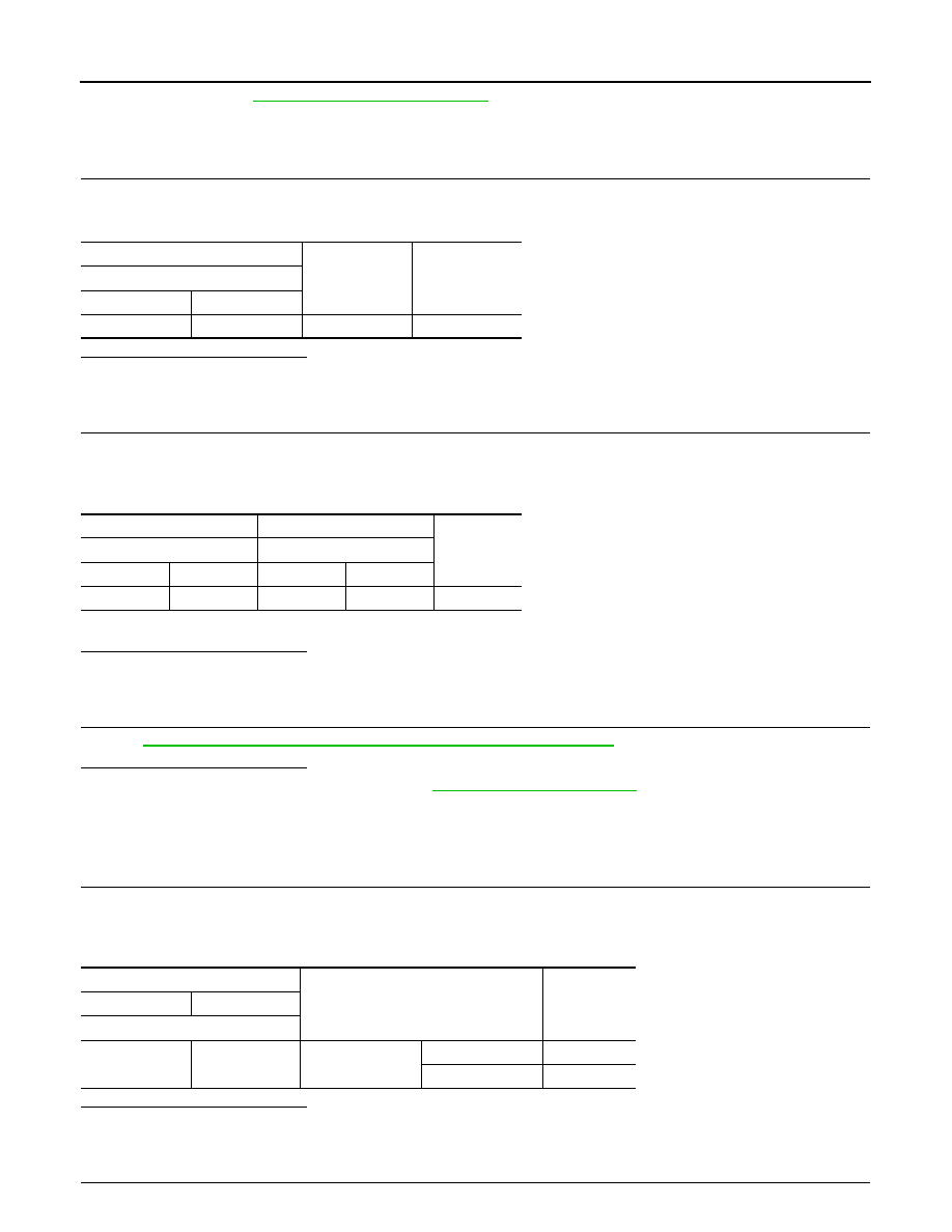
2.
CHECK CLUTCH PEDAL POSITION SWITCH-2
+
-
Continuity
Clutch pedal position switch
Connector
Terminal
E2
2
Ground
Existed
+
-
Continuity
Clutch pedal position switch
ECM
Connector
Terminal
Connector
Terminal
E2
1
E58
9
Existed
Clutch pedal position switch
Condition
Continuity
+
-
Terminal
1
2
Clutch pedal
Fully released
Existed
Slightly depressed
Not existed