Qashqai J11. Drive Mode system - part 2


  Index      Nissan     Qashqai J11. Drive Mode system. Service and Repair Manual


Search            copyright infringement  


Content      ..      1      2     


Qashqai J11. Drive Mode system - part 2


DMS

ECO MODE SWITCH

DMS-17

< DTC/CIRCUIT DIAGNOSIS >

[ECO MODE (CVT)]

C

D

E

F

G

H

I

J

K

L

M

B

N

P

A

7.

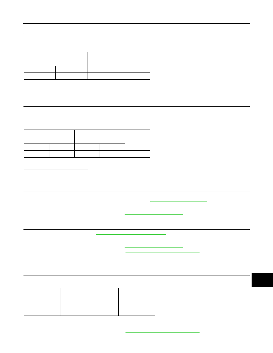
CHECK GROUND CIRCUIT

1.

Turn ignition switch OFF.

2.

Check the continuity between ECO mode switch harness connector and ground.

Is the inspection result normal?

YES

>> GO TO 8.

NO

>> Repair harness or connector.

8.

CHECK CIRCUIT BETWEEN COMBINATION METER AND ECO MODE SWITCH-1

1.

Disconnect combination meter harness connector.

2.

Check continuity between combination meter harness connector terminal and ECO mode switch harness
connector terminal.

3.

Also check harness for short to power and short to ground.

Is the inspection result normal?

YES

>> GO TO 9.

NO

>> Repair or replace damaged parts.

9.

CHECK COMBINATION METER INPUT/OUTPUT SIGNAL

1.

Connect all of disconnected connectors.

2.

Check input/output signal of combination meter. Refer to 

MWI-32, "Reference Value"

.

Is the inspection result normal?

YES

>> Check intermittent incident. Refer to 

GI-41, "Intermittent Incident"

.

NO

>> Repair or replace error detected parts.

10.

CHECK ECO MODE SWITCH

Check ECO mode switch. Refer to 

DMS-17, "Component Inspection"

.

Is the inspection result normal?

YES

>> Check intermittent incident. Refer to 

GI-41, "Intermittent Incident"

.

NO

>> Replace ECO mode switch. Refer to 

DMS-19, "Removal and Installation"

.

Component Inspection

INFOID:0000000010433950

1.

CHECK ECO MODE SWITCH

Check continuity between ECO mode switch connector terminals.

Is the inspection result normal?

YES

>> INSPECTION END

NO

>> Replace ECO mode switch. Refer to 

DMS-19, "Removal and Installation"

.

+

Continuity

ECO mode switch

Connector

Terminal

M109

2

Ground

Existed

+

Continuity

Combination meter

ECO mode switch

Connector

Terminal

Connector

Terminal

M51

9

M109

1

Existed

ECO mode switch

Condition

Continuity

Terminal

1 – 2

ECO mode switch is depressed.

Existed

ECO mode switch is released.

Not existed

DMS-18

< SYMPTOM DIAGNOSIS >

[ECO MODE (CVT)]

THE ECO MODE INDICATOR DOES NOT TURN ON

SYMPTOM DIAGNOSIS

THE ECO MODE INDICATOR DOES NOT TURN ON

Description

INFOID:0000000010433951

The ECO mode indicator does not turn ON when the ECO mode switch is operated.

Diagnosis Procedure

INFOID:0000000010433952

1.

CHECK COMBINATION METER BY ON-BOARD DIAGNOSIS

Perform combination meter on-board diagnosis. Refer to 

MWI-27, "Description"

.

Is the check result normal?

YES

>> GO TO 2.

NO

>> Replace combination meter. Refer to 

MWI-80, "Removal and Installation"

.

2.

CHECK DTC IN TCM

With CONSULT

1.

Start the engine.

2.

Check “Self Diagnostic Results” in “TRANSMISSION”.

Is any DTC detected?

YES

>> Check DTC detected item. Refer to 

TM-267, "DTC Index"

 (RE0F10D) or 

TM-485, "DTC Index"

(RE0F10G).

NO-1

>> MR20DD engine models: GO TO 3.

NO-2

>> Except MR20DD engine models: GO TO 4.

3.

CHECK DTC IN ECM

With CONSULT

Check “Self Diagnostic Results” in “ENGINE”.

Is any DTC detected?

YES

>> Check DTC detected item. Refer to 

ECM-93, "DTC Index"

.

NO

>> GO TO 4.

4.

CHECK DTC IN COMBINATION METER

With CONSULT

Check “Self Diagnostic Results” in “METER/M&A”.

Is any DTC detected?

YES

>> Check DTC detected item. Refer to 

MWI-39, "DTC Index"

.

NO

>> GO TO 5.

5.

CHECK COMBINATION METER INPUT/OUTPUT SIGNAL

With CONSULT

1.

Select “Data Monitor” in “METER/M&A”.

2.

Check that “ECO MODE IND” turns ON/OFF when ECO mode switch is operated. Refer to 

MWI-32, "Ref-

erence Value"

.

Is any DTC detected?

YES

>> Replace combination meter. Refer to 

MWI-80, "Removal and Installation"

.

NO

>> GO TO 6.

6.

CHECK ECO MODE SWITCH SYSTEM

Check ECO mode switch circuit. Refer to 

DMS-15, "Component Function Check"

.

Is the check result normal?

YES

>> INSPECTION END

NO

>> Repair or replace malfunctioning parts.

DMS

ECO MODE SWITCH

DMS-19

< REMOVAL AND INSTALLATION >

[ECO MODE (CVT)]

C

D

E

F

G

H

I

J

K

L

M

B

N

P

A

REMOVAL AND INSTALLATION

ECO MODE SWITCH

Removal and Installation

INFOID:0000000010433953

REMOVAL

1.

Remove instrument lower panel finisher. Refer to 

IP-13, "Removal and Installation"

.

2.

Remove switch holder. Refer to 

IP-12, "Exploded View"

.

3.

Remove ECO mode switch from switch panel, pushing pawls 
of ECO mode switch.
NOTE:
For ECO mode switch design, refer to 

DMS-5, "ECO Mode

Switch"

.

INSTALLATION

Install in the reverse order of removal.

JSOIA1375ZZ


Content      ..      1      2