Qashqai J11. Engine cooling system - part 5
CO-66
< PERIODIC MAINTENANCE >
[K9K]
ENGINE COOLANT
• Never put additive such as waterleak preventive, since it may cause cooling waterway clogging.
• When refilling use Genuine NISSAN Long Life Antifreeze/Coolant (blue) or equivalent in its quality
mixed with water (distilled or demineralized). Refer to
MA-59, "Fluids and Lubricants"
1.
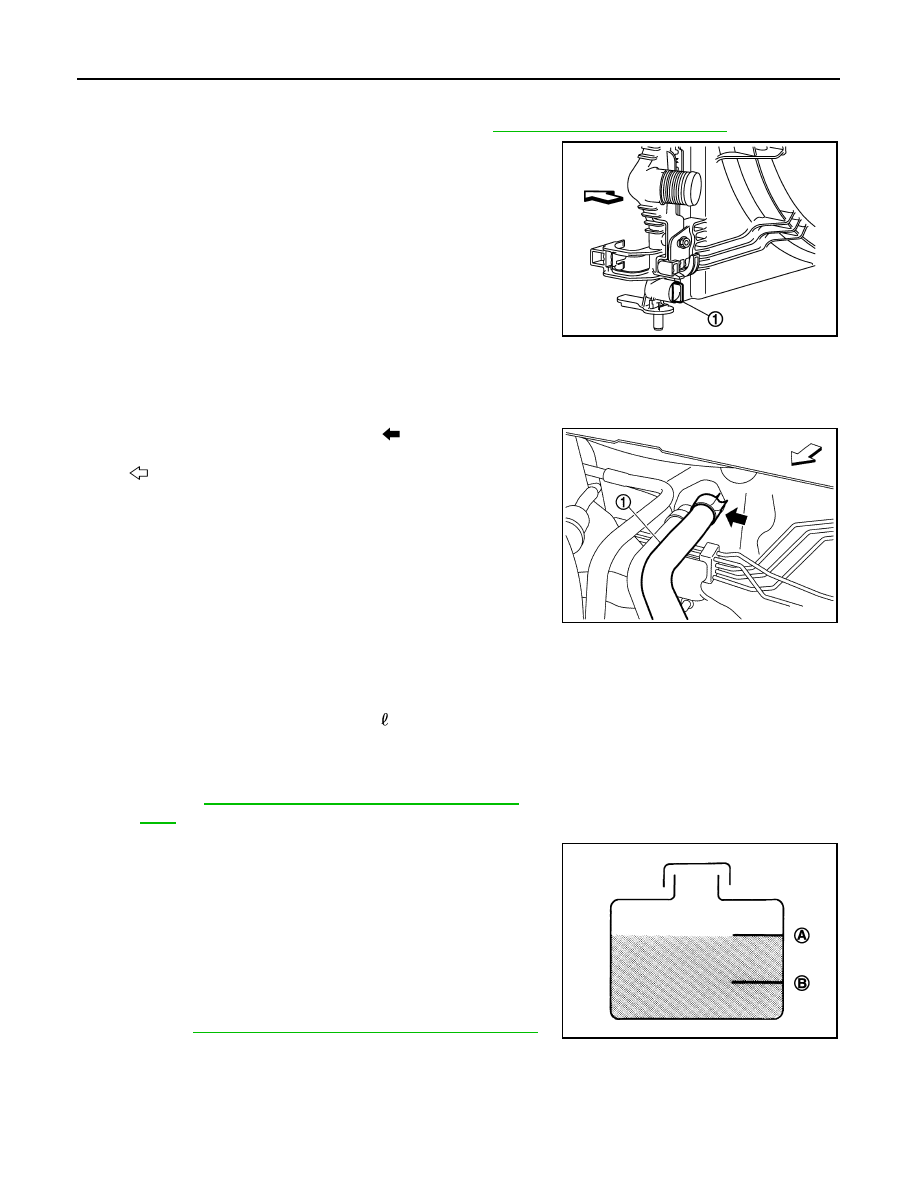
Install reservoir tank if removed and radiator drain plug (1).
CAUTION:
Be sure to clean drain plug and install with new O-ring.
2.
Check that each hose clamp has been firmly tightened.
3.
Disconnect heater hose (1) at position (
) in the figure.
• Enhance heater hose as high as possible.
4.
Fill reservoir tank with engine coolant.
CAUTION:
Never adhere the engine coolant to electronic equipments (alternator etc.).
• Pour coolant slowly of less than 3 (2-5/8 Imp qt) per minute to allow air in system to escape.
•
5.
When engine coolant spill from heater hose with continuous
flow, connect heater hose and continue filling reservoir tank until
reach “MAX” level
6.
7.
Install radiator cap.
8.
Warm up engine at 3000 rpm until thermostat is opened.
• Check thermostat opening condition by touching radiator hose (lower) to see a flow of warm water.
CAUTION:
Watch water temperature gauge so as not to overheat engine.
E1BIA1139ZZ
: Vehicle front
JPBIA4208ZZ
Engine coolant capacity
(With reservoir tank at “MAX” level)
Refer to
CO-81, "Periodical Maintenance Specifica-
.
A
: MAX
B
: MIN
Reservoir tank engine coolant capacity
(At “MAX” level)
Refer to
CO-81, "Periodical Maintenance Specification"
JPBIA0102ZZ