Qashqai J11. Engine cooling system - part 2
RADIATOR
CO-17
< REMOVAL AND INSTALLATION >
[HRA2DDT]
C
D
E
F
G
H
I
J
K
L
M
A
CO
N
P
O
REMOVAL AND INSTALLATION
RADIATOR
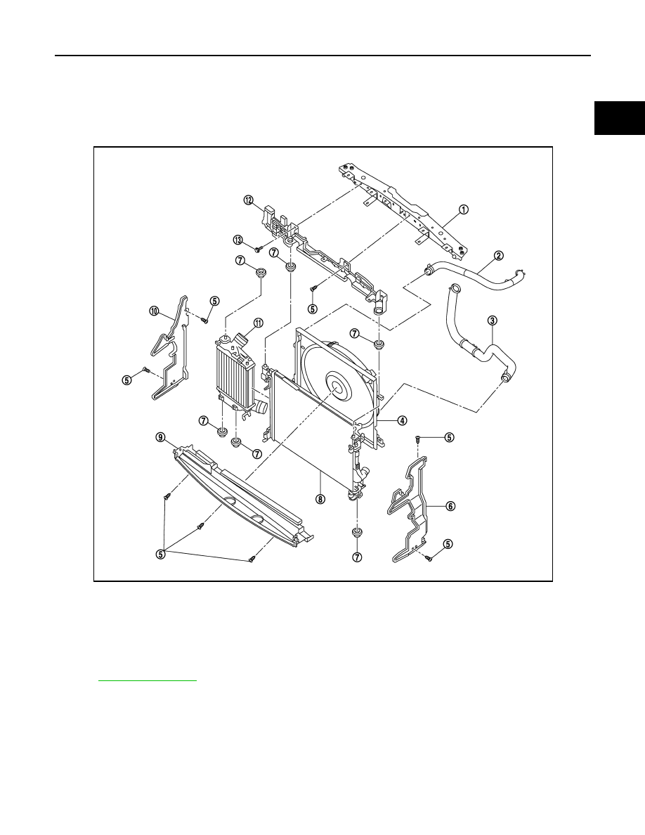
Exploded View
INFOID:0000000010416347
for symbol marks in the figure.
Removal and Installation
INFOID:0000000010416348
REMOVAL
WARNING:
• Never remove reservoir tank cap when engine is hot. Serious burns may occur from high-pressure
engine coolant escaping from radiator.
• Wrap a thick cloth around the reservoir tank cap. Slowly turn it a quarter of a turn to release built-up
pressure. Then turn it all the way.
1.
Radiator core support
2.
Radiator hose (upper)
3.
Radiator hose (lower)
4.
Cooling fan assembly
5.
Clip
6.
Air guide (LH)
7.
Mounting rubber
8.
Radiator
9.
Air guide (Lower)
10. Air guide (RH)
11.
Intercooler
12. Radiator mounting bracket
13. Bolt
E1BIA1116GB