Qashqai J11. Body Control System - part 6
BCS
BCM
BCS-81
< ECU DIAGNOSIS INFORMATION >
C
D
E
F
G
H
I
J
K
L
B
A
O
P
N
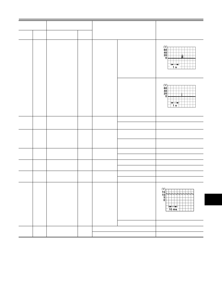
100*
3
(V)
Ground
Driver door antenna
(+)
Output
Power position
ON and any
door is open
Intelligent Key is outside
the vehicle
Intelligent Key is inside
the vehicle
101*
3
(R)
Ground
Push-button ignition
switch (Push switch)
Input
Push-button ig-
nition switch
(push switch)
Pressed
0 – 0.5 V
Not pressed
9 – 16 V
104
(G)
Ground
Front door lock as-
sembly driver side
(Unlock sensor)
Input
Driver door
LOCK status (Unlock sen-
sor switch OFF)
9 – 16 V
UNLOCK status (Unlock
sensor switch ON)
0 – 0.5 V
105*
3
(GR)
Ground
Driver door request
switch
Input
Driver door re-
quest switch
ON (Pressed)
0 – 0.5 V
OFF (Not pressed)
9 – 16 V
105*
4
(GR)
Ground
Key switch (IPDM E/
R)
Input
Power position
ON
0 – 0.5 V
OFF
9 – 16 V
106
(W)
Ground
ACC output
Output
Power position
ACC or ON
0 – 0.5 V
OFF
3.15 V
107
(Y)
Ground
Sensor cancel
switch
Input
Sensor cancel
switch
OFF (Not pressed)
ON (Pressed)
0 V
109*
4
(P)
Ground
NATS antenna amp.
Input/
Output
Just after inserting ignition key in key cylinder
Pointer of tester should move
Other than above
0 V
Terminal No.
(Wire color)
Description
Condition
Value
(Approx.)
+
−
Signal name
Input/
Output
JSMIA1348GB
JSMIA1406GB
JPMIA0011GB