Nissan Qashqai J11. Manual - part 988


  Index      Nissan     Nissan Qashqai J11 - Service and Repair Manual


Search            


Content   ..  986  987  988  989   ..


Nissan Qashqai J11. Manual - part 988


STC-12

< SYSTEM DESCRIPTION >

SYSTEM

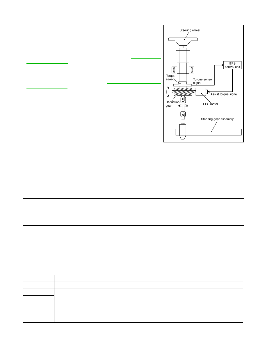
• EPS control unit performs an arithmetical operation on data, such

as steering wheel turning force (sensor signal) from the torque
sensor, vehicle speed signal, etc. Then it generates an optimum
assist torque signal to the EPS motor according to the driving con-
dition.

• In case of an error in the electrical system, the fail-safe function

stops output signals to the EPS motor. Refer to 

STC-12, "EPS

SYSTEM : Fail-safe"

.

• EPS control unit decreases the output signal to EPS motor while

extremely using the power steering function (e.g., full steering)
consecutively for protecting EPS motor and EPS control unit
(Overload protection control). Refer to 

STC-13, "EPS SYSTEM :

Protection Function"

.

• Extensive steering at low speed will cause the ECU and MOTOR

to heat up, once temperature reaches critical point ECU will reduce
current to reduce heat up. System will recover as temperature low-
ers (reduced or no assistance).

• When the driver turns the steering wheel (torque application

exceeding the specified torque) during stop/start, the EPS control
unit restarts the engine (disables stop/start system) and immedi-
ately brings the assist control in its ready-to-start state.

• If EPS becomes out of order, the power steering warning lamp

blinks and the Stop/Start System brings about such conditions as
follows:

- Stop/start mode is not enabled under non stop/start state.
- The engine is restarted during stop/start, regardless of steering wheel operation.
• The Intelligent Parking Assist function provides support for garage parking and parallel parking, and auto-

matically operates the steering wheel when the system is active.

POWER STEERING WARNING LAMP INDICATION

• This light illuminates when the fail-safe function is activated, notifying the driver that there is a malfunction in

the system and that steering state is manual (more force is required to turn the steering wheel).

• Also turns ON when ignition switch is turned ON, for purpose of lamp check. Turns OFF after the engine

starts, if system is normal.

NOTE:
Power steering warning lamp also turns ON due to data reception error, CAN communication error etc.

EPS SYSTEM : Fail-safe

INFOID:0000000010470621

• If any malfunction occurs in the system and control unit detects the malfunction, power steering warning

lamp on combination meter turns ON to indicate system malfunction.

• When power steering warning lamp is ON, the system enters into a manual steering state. (Control turning

force steering wheel becomes heavy.)

JMGIA0185GB

Condition

Power steering warning lamp

Ignition switch ON. (Lamp check)

ON

Engine running.

OFF

EPS system malfunction [Other diagnostic item]

ON

DTC

Fail-safe condition

C1601

The assist force is reduced according to the voltage, eventually ending with manual steering state

C1604

Manual steering state

C1606

C1607

C1608

C1609

Non-speed sensitive steering assist

SYSTEM

STC-13

< SYSTEM DESCRIPTION >

C

D

E

F

H

I

J

K

L

M

A

B

STC

N

O

P

EPS SYSTEM : Protection Function

INFOID:0000000010470622

EPS control unit decreases the output signal to EPS motor while extremely using the power steering function
(e.g., full steering) consecutively for protecting EPS motor and EPS control unit (Overload protection control).
While activating overload protection control, the assist torque gradually decreases, and the steering wheel
turning force becomes heavy. The normal assist torque reactivates by no steering.

U1000

• Non-speed sensitive steering assist
• Intelligent Parking Assist function (controlled from around view monitor) or Stop/Start system function (controlled 

from ECM) is stopped

U1010

Normal control

U1970

Intelligent Parking Assist function (controlled from around view monitor) is stopped

DTC

Fail-safe condition

STC-14

< SYSTEM DESCRIPTION >

DIAGNOSIS SYSTEM (EPS CONTROL UNIT)

DIAGNOSIS SYSTEM (EPS CONTROL UNIT)

CONSULT Function

INFOID:0000000010452105

FUNCTION

CONSULT can display each diagnostic item using the diagnostic test modes shown following.

*: The following diagnosis information is erased by erasing.
• DTC
• Freeze frame data (FFD)

ECU IDENTIFICATION

Displays the part number stored in the control unit.

SELF-DIAG RESULTS MODE

Refer to 

STC-19, "DTC Index"

.

When “CRNT” is displayed on self-diagnosis result.

• The system is presently malfunctioning.

When “PAST” is displayed on self-diagnosis result.

• System malfunction in the past is detected, but the system is presently normal.

FREEZE FRAME DATA (FFD)

The following vehicle status is recorded when DTC is detected and is displayed on CONSULT.

DATA MONITOR MODE

NOTE:
The following table includes information (items) inapplicable to this vehicle. For information (items) applicable
to this vehicle, refer to CONSULT display items.

Diagnostic test mode

Function

ECU identification

The part number stored in the control unit can be read.

Self diagnostic result

Self-diagnostic results and freeze frame data can be read and erased quickly.

*

Data monitor

Input/Output data in the EPS control unit can be read.

Item name

Display item

IGN COUNTER
(0 – 39)

The number of times that ignition switch is turned ON after the DTC is detected is displayed.
• When “0” is displayed: It indicates that the system is presently malfunctioning.
• When except “0” is displayed: It indicates that system malfunction in the past is detected, but the system is pres-

ently normal.
NOTE:
Each time when ignition switch is turned OFF to ON, numerical number increases in 1

2

3...38

39.

When the operation number of times exceeds 39, the number do not increase and “39” is displayed until self-
diagnosis is erased.

Monitor item (Unit)

Remarks

BATTERY VOLT (V)

Displays the power supply voltage for EPS control unit.

TORQUE SENSOR (Nm)

Displays steering wheel turning force detected by torque sensor.

MOTOR CURRENT (A)

Displays the current value consumed by EPS motor.

*1

MOTOR SIG (A)

Displays the current commanded value to EPS motor.

ASSIST TORQUE (Nm)

Displays assist torque being output by the electric power steering.

C/U TEMP [

°

C (

°

F)]

Displays the temperature of the EPS control unit.

ASSIST LEVEL (%)

Normally displays 100%. In case of an excessive stationary steering, the assist 

curvature gradually falls. However, it return to 100% when left standing.

*2

VEHICLE SPEED [km/h (MPH)]

Vehicle speed is displayed from vehicle speed signal via CAN communication.

*3

WARNING LAMP (On/Off)

Power steering warning lamp control status is displayed.

ENGINE STATUS (Stop/Run)

Engine speed is displayed from engine status signal via CAN communication.

DIAGNOSIS SYSTEM (EPS CONTROL UNIT)

STC-15

< SYSTEM DESCRIPTION >

C

D

E

F

H

I

J

K

L

M

A

B

STC

N

O

P

*1: Almost in accordance with the value of “MOTOR SIG”. It is not a malfunction though these values are not
accorded when steering quickly.
*2: Normally displays 100%. In case of an excessive stationary steering, the assist curvature gradually falls.
However, it returns to 100% when left standing.
*3: It is not a malfunction, though it might not be corresponding just after ignition switch in turned ON.

ST TORQUE STATUS (On/Off)

Displays steering status.

EPS ASSIST PERMIS (On/Off)

Displays assist permission status of EPS system.

STOP/START STATUS (INACT/AUTO ST/ACT/
CANCEL)

Displays stop/start status.

IPA ON (Off 1/Off 2/Off 3/On)

Displays Intelligent Parking Assist status.

IPA STATUS 1 (On/Off)

Displays operating status of Intelligent Parking Assist

STOP/START SYSTEM (On/Off)

Displays permission status of stop/start system.

IPA STATUS 2 (Off/On 1/On 2)

Displays operating status of Intelligent Parking Assist.

IPA STATUS 3 (NORMAL/MALF)

Displays Intelligent Parking Assist status.

IPA TARGET CURRENT (A)

Displays the command current value from Intelligent Parking Assist.

EPS CONTROL CURRENT (A)

Displays motor current value.

Monitor item (Unit)

Remarks


Content   ..  986  987  988  989   ..