Nissan Qashqai J11. Manual - part 967
C1160 DECEL G SEN SET
BRC-105
< DTC/CIRCUIT DIAGNOSIS >
[WITH ESP]
C
D
E
G
H
I
J
K
L
M
A
B
BRC
N
O
P
C1160 DECEL G SEN SET
DTC Logic
INFOID:0000000010329844
DTC DETECTION LOGIC
DTC CONFIRMATION PROCEDURE
1.
CHECK SELF-DIAGNOSTIC RESULT
With CONSULT.
1.
Turn ignition switch OFF to ON.
2.
Perform self-diagnostic result.
Is DTC C1160 detected?
YES
>> Proceed to diagnosis procedure. Refer to
BRC-105, "Diagnosis Procedure"
NO
>> Inspection End.
Diagnosis Procedure
INFOID:0000000010329845
1.
DECEL G SENSOR CALIBRATION
Perform decel G sensor calibration. Refer to
>> GO TO 2.
2.
CHECK SELF-DIAGNOSTIC RESULT
With CONSULT.
Perform self-diagnostic result.
Is DTC C1160 detected?
YES
>> GO TO 3.
NO
>> Inspection End.
3.
CHECK YAW RATE/SIDE/DECEL G SENSOR SYSTEM
Check yaw rate/side/decel G sensor system. Refer to
Is the inspection result normal?
YES
>> Replace ABS actuator and electric unit (control unit). Refer to
BRC-142, "Removal and Installa-
.
NO
>> Repair or replace malfunctioning components.
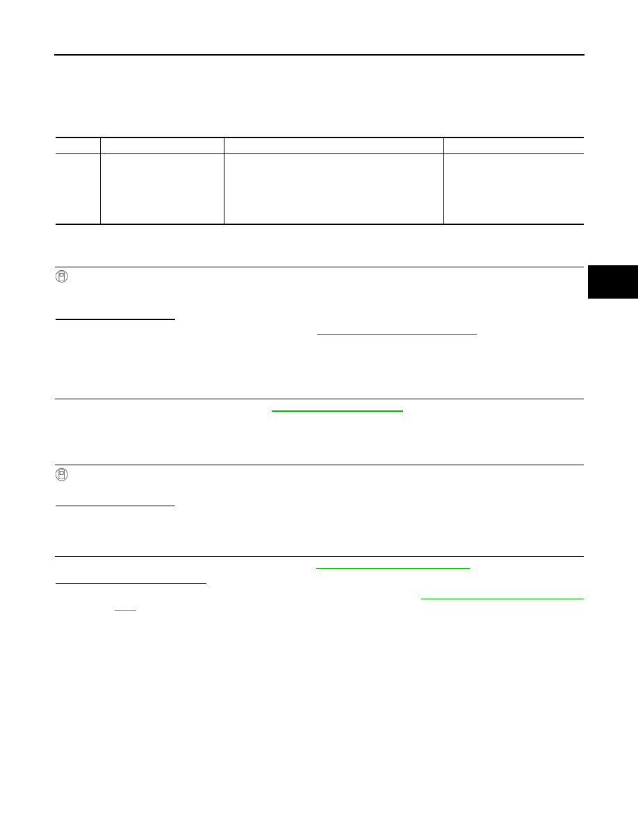
DTC
Display Item
Malfunction detected condition
Possible causes
C1160
DECEL G SEN SET
When calibration of yaw rate/side/decel G sensor is
not complete.
• Yaw rate/side/decel G sensor
• Harness or connector
• ABS actuator and electric unit
(control unit)
• Decel G sensor calibration is
not performed