Nissan Qashqai J11. Manual - part 959
C1101, C1102, C1103, C1104 WHEEL SENSOR
BRC-73
< DTC/CIRCUIT DIAGNOSIS >
[WITH ESP]
C
D
E
G
H
I
J
K
L
M
A
B
BRC
N
O
P
*1: With TC models
*2: With HT models
Is the inspection result normal?
YES
>> GO TO 7.
NO
>> Repair the circuit.
7.
CHECK WIRING HARNESS FOR SHORT BETWEEN CIRCUITS
Check continuity between wheel sensor harness connector terminals of suspect wheel.
*1: With TC models
*2: With HT models
Is the inspection result normal?
YES
>> GO TO 8.
NO
>> Repair the circuit.
8.
CHECK WIRING HARNESS FOR OPEN CIRCUIT
Check continuity between ABS actuator and electric unit (control unit) harness connector E18 and harness
connector of suspect wheel sensor.
*1: With TC models
*2: With HT models
Is the inspection result normal?
YES
>> GO TO 9.
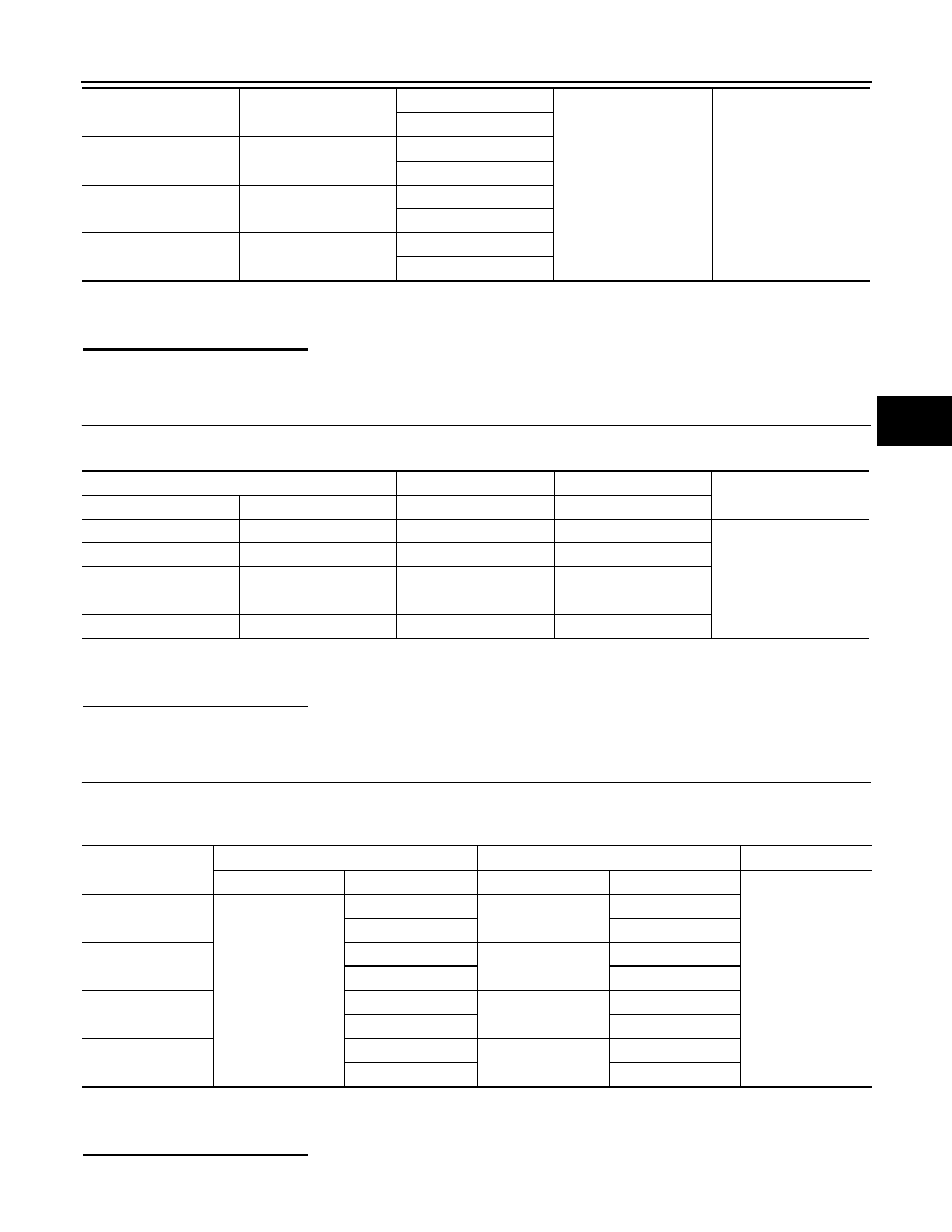
Front LH
E53
1
—
No
2
Front RH
E54
3
4
Rear LH
B38
*1
B39
*2
5
6
Rear RH
B30
7
8
Wheel Sensor
(+)
(-)
Continuity
Wheel
Connector
Terminal
Terminal
Front LH
E53
1
2
No
Front RH
E54
3
4
Rear LH
B38
*1
B39
*2
5
6
Rear RH
B30
7
8
Wheel sensor
ABS actuator and electric unit (control unit)
Wheel sensor
Continuity
Connector
Terminal
Connector
Terminal
Yes
Front LH
E18
19
E53
1
8
2
Front RH
16
E54
3
4
4
Rear LH
31
B38
*1
B39
*2
5
18
6
Rear RH
17
B30
7
29
8