Nissan Qashqai J11. Manual - part 890
BR-32
< REMOVAL AND INSTALLATION >
[LHD]
VACUUM LINES
VACUUM LINES
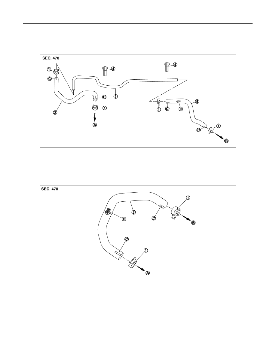
Exploded View
INFOID:0000000010450968
MR20DD - HRA2DDT
K9K
JPFIA0127ZZ
1.
Clamp
2.
Vacuum hose
3.
Vacuum tube
4.
Clip
5.
Vacuum hose
A.
To intake manifold
B.
To brake booster
C.
Paint mark
D.
Stamp indicating engine direction
JPFIA0085ZZ
1.
Clamp
2.
Vacuum hose
A.
To vacuum pump
B.
To brake booster
C.
Paint mark
D.
Stamp indicating engine direction