Nissan Qashqai J11. Manual - part 860


  Index      Nissan     Nissan Qashqai J11 - Service and Repair Manual


Search            


Content   ..  858  859  860  861   ..


Nissan Qashqai J11. Manual - part 860


WHEEL ALIGNMENT

RSU-5

< PERIODIC MAINTENANCE >

C

D

F

G

H

I

J

K

L

M

A

B

RSU

N

O

P

WHEEL ALIGNMENT

Wheel Alignment Inspection

INFOID:0000000010297254

INSPECTION

Description

Measure wheel alignment under unladen conditions. 
NOTE:
“Unladen conditions” means that fuel, engine coolant, and lubricant are full. Spare tire, jack, hand tools and
mats are in designated positions.

Preliminary Check

Check the following:
• Tires for improper air pressure and wear
• Road wheels for runout: Refer to 

WT-60, "Inspection"

.

• Wheel bearing axial end play: Refer to 

RAX-3, "Inspection"

 (2WD), 

RAX-10, "Inspection"

 (4WD).

• Shock absorber operation
• Each mounting point of axle and suspension for looseness and deformation
• Each of lower link, upper link, rear suspension member, suspension arm and shock absorber for cracks,

deformation, and other damage

• Vehicle height (posture)
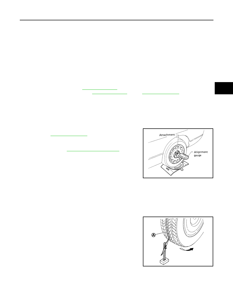
Camber

• Measure camber of both right and left wheels with a suitable alignment gauge.
• If camber exceeds the standard value, adjust with adjusting bolt in

lower. Refer to 

RSU-6, "Adjustment"

.

Toe-In

Measure toe-in by the following procedure.

WARNING:

• Always perform the following procedure on a flat surface.
• Make sure that no person is in front of vehicle before pushing it.
1.

Bounce the front of vehicle up and down to stabilize the vehicle height (posture).

2.

Push vehicle straight ahead about 5 m (16 ft).

3.

Put matching mark (A) on base line of the tread (rear side) of
both tires at the same height of hub center. These are measur-
ing points.

Standard

Camber: Refer to 

RSU-21, "Wheel Alignment"

.

SRA096A

JPEIA0014ZZ

RSU-6

< PERIODIC MAINTENANCE >

WHEEL ALIGNMENT

4.

Measure distance (A) (rear side).

5.

Push vehicle slowly ahead to rotate wheels 180 degrees (1/2
turn).
NOTE:
If the wheels rotates more than 180 degrees (1/2 turn), start this
procedure again from the beginning. Do not push the vehicle
backward.

6.

Measure distance (B) (front side).

• If toe-in exceeds the standard value, adjust with adjusting bolt in suspension arm.

Adjustment

INFOID:0000000010297255

CAMBER

If camber exceeds the standard value, adjust with adjusting bolt (1)
in lower link (2).

CAUTION:

After adjusting camber, be sure to check toe-in.

• If camber exceeds the standard value, inspect and replace any

damaged or worn suspension parts.

TOE-IN

If toe-in exceeds the standard value, adjust with adjusting bolt (1) in
suspension arm (2).

CAUTION:

Be sure to adjust equally on RH and LH side with adjusting bolt.
• If toe-in exceeds the standard value, inspect and replace any dam-

aged or worn suspension parts.

Standard

Total toe-in: Refer to 

RSU-21, "Wheel Align-

ment"

.

JPEIA0015ZZ

Standard

Camber: Refer to 

RSU-21, "Wheel Alignment"

.

JPEIB0025ZZ

Standard

Toe-In: Refer to 

RSU-21, "Wheel Alignment"

.

JPEIB0024ZZ

COIL SPRING

RSU-7

< REMOVAL AND INSTALLATION >

C

D

F

G

H

I

J

K

L

M

A

B

RSU

N

O

P

REMOVAL AND INSTALLATION

COIL SPRING

Exploded View

INFOID:0000000010297256

FOR 2WD EUROPE (HT)

FOR 2WD GOM and 4WD (TC)

Removal and Installation

INFOID:0000000010297257

REMOVAL

E1EIA0117GB

1.

Upper rubber seat

2.

Coil spring

3.

Lower seat

4.

Rear suspension arm

Refer to 

GI-4, "Components"

 for symbols in the figure.

AWEIA0351ZZ

1.

Upper rubber seat

2.

Coil spring

3.

Lower seat

4.

Rubber washer (LH/RH)

5.

Rear suspension arm

: Front

Refer to 

GI-4, "Components"

 for symbols in the figure.

RSU-8

< REMOVAL AND INSTALLATION >

COIL SPRING

1.

Remove tires from vehicle.

2.

Remove torque member mounting bolts. Hang torque member where it does not interfere with work. Refer
to 

BR-43, "BRAKE CALIPER ASSEMBLY : Exploded View"

 (LHD), 

BR-86, "BRAKE CALIPER ASSEM-

BLY : Exploded View"

 (RHD).

CAUTION:

Never depress brake pedal while brake caliper is removed.

3.

Remove wheel sensor from axle housing. Refer to 

BRC-139, "REAR WHEEL SENSOR : Exploded View"

.

4.

Set suitable jack under suspension arm.

5.

Remove shock absorber from suspension arm. Refer to 

RSU-9, "Exploded View"

.

6.

Remove lower link from suspension arm. Refer to 

RSU-13, "Exploded View"

.

7.

Remove upper link from suspension arm. Refer to 

RSU-15, "Exploded View"

.

8.

Remove drive shaft (4WD). Refer to 

RAX-14, "Exploded View"

.

9.

Remove coil spring from vehicle.

INSTALLATION

Note the following, and install in the reverse order of removal.
• Match up lower rubber seat indentions and suspension arm

grooves and attach.

• Install coil spring by aligning lower end of the large diameter side to

step between lower rubber seat and suspension arm.

• Perform the final tightening of rear suspension member and axle

installation position (rubber bushing) under unladen condition with
tires on level ground.

Inspection

INFOID:0000000010297258

INSPECTION AFTER REMOVAL

Check lower link, bushing and coil spring for deformation, crack, and damage. Replace it if necessary.

INSPECTION AFTER INSTALLATION

1.

Check wheel alignment. Refer to 

RSU-5, "Wheel Alignment Inspection"

.

2.

Adjust neutral position of steering angle sensor. Refer to 

BRC-66, "Work Procedure"

 .

SEIA0636J


Content   ..  858  859  860  861   ..