Nissan Qashqai J11. Manual - part 822
DLN-204
< REMOVAL AND INSTALLATION >
[REAR FINAL DRIVE: R145]
ELECTRIC CONTROLLED COUPLING
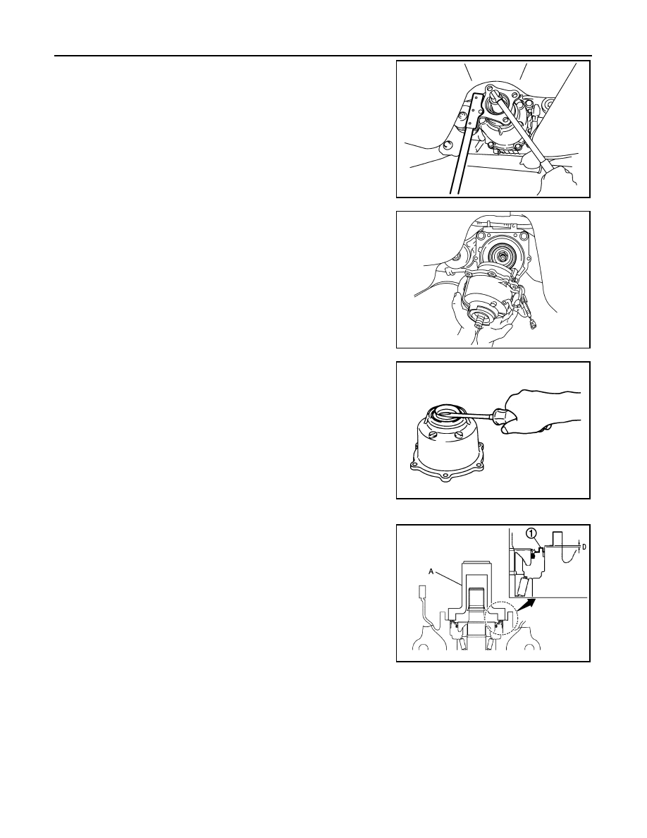
5.
Remove companion flange lock nut, using a flange wrench
(commercial service tool).
6.
Remove companion flange.
7.
Remove electric controlled coupling breather hose from cou-
pling cover.
8.
Remove coupling cover with electric controlled coupling from
final drive assembly.
9.
Remove electric controlled coupling from coupling cover.
10. Remove 4WD solenoid harness.
11. Remove front oil seal from coupling cover, using a flat-bladed
screwdriver.
CAUTION:
Be careful not to damage coupling cover.
12. Remove center oil seal from final drive assembly.
INSTALLATION
1.
Using the drift (A) (SST: ST35271000), install center oil seal (1)
as shown in the figure.
CAUTION:
• Never reuse oil seal.
• When installing, never incline oil seal.
• Apply multi-purpose grease onto oil seal lips, and gear oil
onto the circumference of oil seal.
2.
Connect 4WD solenoid harness to electric controlled coupling.
JSDIA0199ZZ
PDIA0458E
PDG0213D
Dimension “D”
: 0.8 – 1.2 mm (0.031 – 0.047 in)
JSDIA0260ZZ