Nissan Qashqai J11. Manual - part 814
DLN-172
< UNIT DISASSEMBLY AND ASSEMBLY >
[TRANSFER: TY30A]
DRIVE PINION
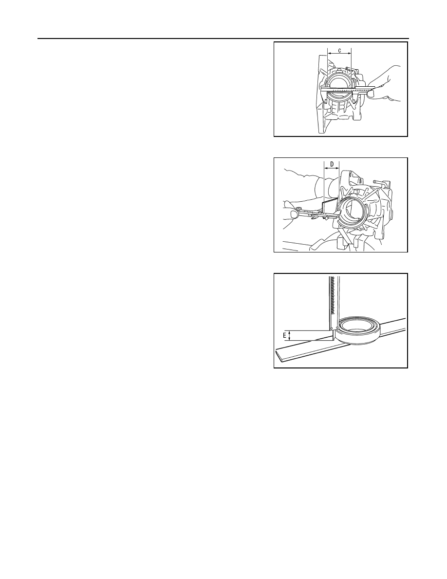
• Measure the diameter of drive pinion bearing (rear side)
mounting area of transfer case with a pair of vernier calipers.
Refer to “Measuring point”.
CAUTION:
Never damage transfer case.
Dimension “D” measurement
• Measure dimension from adapter case mounting surface of
transfer case to drive pinion bearing (rear side) mounting sur-
face with a pair of vernier calipers and straightedge. Refer to
“Measuring point”.
CAUTION:
• Never damage transfer case.
• Consider the thickness of a straightedge.
Dimension “E” measurement
• Measure dimension from outer race edge surface of ring gear
shaft bearing (adapter case side) to inner race edge surface
with a pair of vernier calipers. Refer to “Measuring point”.
2.
Calculate dimensions “M” and “N” by the formula below.
3.
Convert the dimensions “E”, “M” and “N” according to the standards below.
SDIA3107J
SDIA3108J
SDIA3109J
Dimension “M” = “A” – “B”
Dimension “N” = “C”
×
0.5 mm (0.020 in) + “D”
“E”
: Actual value regarding 20.00 mm (0.7874 in) as 0 in increments of 0.01 mm (0.0004 in).
“M”
: Actual value regarding 13.90 mm (0.5472 in) as 0 in increments of 0.01 mm (0.0004 in).
“N”
: Actual value regarding 55.00 mm (2.1654 in) as 0 in increments of 0.01 mm (0.0004 in).