Nissan Qashqai J11. Manual - part 754


  Index      Nissan     Nissan Qashqai J11 - Service and Repair Manual


Search            


Content   ..  752  753  754  755   ..


Nissan Qashqai J11. Manual - part 754


P1890 ELECTRIC OIL PUMP RELAY

TM-591

< DTC/CIRCUIT DIAGNOSIS >

[CVT: RE0F10G]

C

E

F

G

H

I

J

K

L

M

A

B

TM

N

O

P

NO

>> GO TO 6.

3.

CHECK CIRCUIT BETWEEN TCM AND ELECTRIC OIL PUMP RELAY (PART 1)

1.

Disconnect the TCM connector.

2.

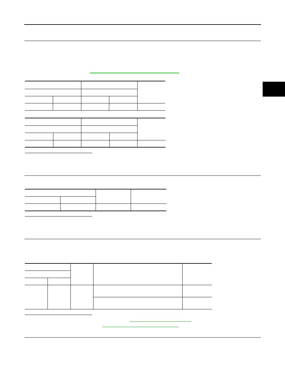
Check continuity between TCM harness connector terminal and electric oil pump relay harness connector
terminal.
NOTE:
• A diode is located between TCM and the electric oil pump relay.
• To check diode, refer to 

TM-592, "Component Inspection (Diode)"

.

Is the inspection result normal?

YES 

>> GO TO 4.

NO

>> Repair or replace malfunctioning parts.

4.

CHECK CIRCUIT BETWEEN TCM AND ELECTRIC OIL PUMP RELAY (PART 2)

Check continuity between the electric oil pump relay harness connector terminal and ground.

Is the inspection result normal?

YES 

>> GO TO 5.

NO

>> Repair or replace malfunctioning parts.

5.

CHECK ELECTRIC OIL PUMP RELAY SIGNAL

1.

Install the electric oil pump relay.

2.

Connect the TCM connector.

3.

Check the voltage between the TCM harness connector terminal and ground.

Is the inspection result normal?

YES 

>> Check intermittent incident. Refer to 

GI-41, "Intermittent Incident"

.

NO

>> Replace TCM. Refer to 

TM-625, "Removal and Installation"

.

6.

DETECTION OF MALFUNCTION ITEMS

Check the following items:

• Fuse block (J/B)

+

Continuity

TCM

Electric oil pump relay

Connector

Terminal

Connector

Terminal

F1

1

F119

2

Existed

+

Continuity

Electric oil pump relay

TCM

Connector

Terminal

Connector

Terminal

F119

2

F1

1

Not  existed

Electric oil pump relay

Continuity

Connector

Terminal

F119

2

Ground

Not existed

+

Condition

Voltage

TCM

Connector

Terminal

F1

1

Ground

• Selector lever: “D”position
• Vehicle speed: 11 km/h (7 MPH) or more

10 – 16 V

• Selector lever: “D”position
• Vehicle speed: 6 km/h (3 MPH) or less

Approx. 0 V

TM-592

< DTC/CIRCUIT DIAGNOSIS >

[CVT: RE0F10G]

P1890 ELECTRIC OIL PUMP RELAY

• 10A fuse [No. 79, located in fuse block (J/B)] Refer to 

PG-97, "Fuse, Connector and Terminal Arrangement"

.

• Open circuit or short circuit in harness between battery positive terminal and electric oil pump relay harness

connector. Refer to 

PG-11, "Wiring Diagram - BATTERY POWER SUPPLY -"

.

• Battery

Is the inspection result normal?

YES

>> Check intermittent incident. Refer to 

GI-41, "Intermittent Incident"

.

NO

>> Repair or replace malfunctioning parts.

Component Inspection (Electric Oil Pump Relay)

INFOID:0000000010249650

1.

ELECTRIC OIL PUMP RELAY

1.

Remove the electric oil pump relay. Refer to 

TM-430, "CVT CONTROL SYSTEM : Component Parts

Location"

.

2.

Apply voltage of 12 V between the electric oil pump relay connector terminals 1 and 2.

CAUTION:

• Never cause shorting between terminals.
• When applying voltage, put a fuse between terminals.

3.

Check continuity between the electric oil pump relay connector terminals 3 and 5.

Is the check result normal?

YES >> INSPECTION 

END

NO

>> Replace the electric oil pump relay. Refer to 

TM-430, "CVT CONTROL SYSTEM : Component

Parts Location"

.

Component Inspection (Diode)

INFOID:0000000010249651

• Check continuity with a tester. 
• The diode is normal if the result is as shown in the figure when the

polarity is reversed. 

NOTE:
Tester specifications may vary depending on the tester type. Refer to
the handling manual of the tester before checking continuity.

Electric oil pump relay

Condition

Continuity

Terminal

3

5

Apply voltage between terminals 1 and 2.

Existed

Do not apply voltage between terminals 1 and 2.

Not existed

JSDIA2056GB

P2765 INPUT SPEED SENSOR B

TM-593

< DTC/CIRCUIT DIAGNOSIS >

[CVT: RE0F10G]

C

E

F

G

H

I

J

K

L

M

A

B

TM

N

O

P

P2765 INPUT SPEED SENSOR B

DTC Logic

INFOID:0000000010245651

DTC DETECTION LOGIC

DTC CONFIRMATION PROCEDURE

CAUTION:

Be careful of the driving speed.

1.

PREPARATION BEFORE WORK

If another "DTC CONFIRMATION PROCEDURE" occurs just before, turn ignition switch OFF and wait for at
least 10 seconds, then perform the next test.

DTC

CONSULT screen terms

(Trouble diagnosis content)

DTC detection condition

Possible causes

P2765

INPUT SPEED SENSOR B
(Input/Turbine Speed Sensor 
B Circuit)

When 1 is satisfied and any of 2, 3 or 4 is sat-
isfied and this state is maintained for 5 sec-
onds:
1.

When all of the following conditions are 
satisfied:

-

TCM power supply voltage: More than 11 
V

-

After range change completion, it spends 
2 seconds or more.

2.

When all of the following conditions are 
satisfied and this state is maintained for 
5 seconds:

-

Secondary pulley speed: Less than 150 
rpm

-

Primary pulley speed: 1,000 rpm or more

3.

When all of the following conditions are 
satisfied and this state is maintained for 
0.5 seconds:

-

10-msec-ago secondary pulley speed: 
1000 rpm or more

-

Now secondary pulley speed: 0 rpm

4.

When all of the following conditions are 
satisfied and this state is maintained for 
5 seconds:

-

Range: D or Ds

-

Engine speed: 450 rpm or more

-

Primary pulley speed: 300 rpm or more

-

Secondary pulley speed: 300 rpm or 
more

-

Input speed: 300 rpm or more

-

The difference between engine speed 
and primary pulley speed is 1,000 rpm or 
less

-

The difference between engine speed 
and input speed is 1,000 rpm or less

-

The difference between primary pulley 
speed and input speed is 1,000 rpm or 
less

-

Lock-up command is being given (except 
for slip lock-up)

-

DTC other than the applicable DTC is not 
detected.

-

 When any of following items are satis-
fied:

Primary pulley speed/secondary pulley 
speed: More than 2.9

Primary pulley speed/secondary pulley 
speed: Less than 0.3

• Harness or connector

(Output speed sensor circuit is open or 
shorted) 

• Output speed sensor

TM-594

< DTC/CIRCUIT DIAGNOSIS >

[CVT: RE0F10G]

P2765 INPUT SPEED SENSOR B

>> GO TO 2.

2.

CHECK DTC DETECTION

1.

Start the engine.

2.

Drive the vehicle.

3.

Maintain the following conditions for 10 seconds or more.

4.

Stop the vehicle.

5.

Check the first trip DTC.

Is “P2765” detected?

YES

>> Go to 

TM-594, "Diagnosis Procedure"

.

NO

>> INSPECTION END

Diagnosis Procedure

INFOID:0000000010245652

1.

CHECK OUTPUT SPEED SENSOR POWER CIRCUIT 

1.

Turn ignition switch OFF.

2.

Disconnect output speed sensor connector.

3.

Turn ignition switch ON.

4.

Check voltage between output speed sensor harness connector terminal and ground. 

Is the inspection result normal?

YES 

>> GO TO 2.

NO

>> GO TO 6.

2.

CHECK OUTPUT SPEED SENSOR GROUND CIRCUIT 

Check continuity between output speed sensor harness connector terminal and ground. 

Is the inspection result normal?

YES 

>> GO TO 3.

NO

>> Repair or replace malfunctioning parts.

3.

CHECK CIRCUIT BETWEEN OUTPUT SPEED SENSOR AND TCM (PART 1)

1.

Turn ignition switch OFF.

2.

Disconnect TCM connector.

3.

Check continuity between output speed sensor harness connector terminal and TCM harness connector
terminal.

Is the inspection result normal?

Selector lever

: “D” position

Engine speed

: 1,200 rpm or more

Vehicle speed

: 55 km/h (34 MPH) or more

+

Voltage

Output speed sensor

Connector

Terminal

F41

3

Ground

10 – 16 V

Output speed sensor

Continuity

Connector

Terminal

F41

1

Ground

Existed

Output speed sensor

TCM

Continuity

Connector

Terminal

Connector

Terminal

F41

2

F1

34

Existed


Content   ..  752  753  754  755   ..