Nissan Qashqai J11. Manual - part 745


  Index      Nissan     Nissan Qashqai J11 - Service and Repair Manual


Search            


Content   ..  743  744  745  746   ..


Nissan Qashqai J11. Manual - part 745


P0826 UP AND DOWN SHIFT SW

TM-555

< DTC/CIRCUIT DIAGNOSIS >

[CVT: RE0F10G]

C

E

F

G

H

I

J

K

L

M

A

B

TM

N

O

P

Is the inspection result normal?

YES

>> Check intermittent incident. Refer to 

GI-41, "Intermittent Incident"

.

NO

>> Repair or replace damaged parts.

5.

CHECK GROUND CIRCUIT

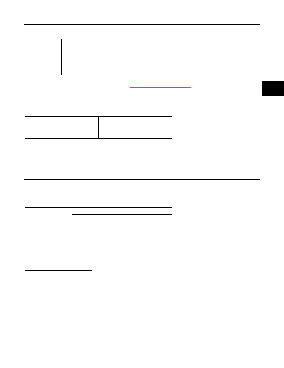
Check continuity between CVT shift selector harness connector terminal and ground.

Is the inspection result normal?

YES

>> Check intermittent incident. Refer to 

GI-41, "Intermittent Incident"

.

NO

>> Repair or replace damaged parts.

Component Inspection

INFOID:0000000010438741

1.

MANUAL MODE SWITCH

Check continuity between CVT shift selector connector terminals.

Is the inspection result normal?

YES

>> INSPECTION END

NO

>> Replace the CVT shift selector assembly due to malfunction in manual mode switch. Refer to 

TM-

617, "Removal and Installation"

.

CVT shift selector

Continuity

Connector

Terminal

M9

7

Ground

Not existed

8

9

11

CVT shift selector

Continuity

Connector

Terminal

M9

10

Ground

Existed

CVT shift selector

Condition

Continuity

Terminal

7 – 10

Manual shift gate position (neutral)

Existed

Other than the above

Not existed

8 – 10

Selector lever: DOWN (

 side)

Existed

Other than the above

Not existed

9 – 10

Selector lever: UP (+ side)

Existed

Other than the above

Not existed

11 – 10

Manual shift gate position

Not existed

Other than the above

Existed

TM-556

< DTC/CIRCUIT DIAGNOSIS >

[CVT: RE0F10G]

P0841 TRANSMISSION FLUID PRESSURE SEN/SW A

P0841 TRANSMISSION FLUID PRESSURE SEN/SW A

DTC Logic

INFOID:0000000010245627

DTC DETECTION LOGIC

DTC CONFIRMATION PROCEDURE

CAUTION:

Always drive vehicle at a safe speed.

1.

PREPARATION BEFORE WORK

If another “DTC CONFIRMATION PROCEDURE” occurs just before, turn ignition switch OFF and wait for at
least 10 seconds, then perform the next test.

>> GO TO 2.

2.

CHECK DTC DETECTION

1.

Start the engine.

2.

Drive the vehicle.

3.

Maintain the following condition for 10 seconds or more.

CAUTION:

Also keep the accelerator pedal position constant.

4.

Stop the vehicle.

5.

Check the first trip DTC.

Is “P0841” detected?

YES

>> Go to 

TM-556, "Diagnosis Procedure"

.

NO

>> INSPECTION END

Diagnosis Procedure

INFOID:0000000010245628

1.

CHECK INTERMITTENT INCIDENT

Refer to 

GI-41, "Intermittent Incident"

.

Is the inspection result normal?

YES

>> Replace the transaxle assembly. Refer to 

TM-653, "Removal and Installation"

.

NO

>> Repair or replace damaged parts.

DTC

CONSULT screen terms

(Trouble diagnosis content)

DTC detection condition

Possible cause

P0841

FLUID PRESS SEN/SW A
(Transmission Fluid Pres-
sure Sensor/Switch “A” Cir-
cuit Range/Performance)

When all of the following conditions are sat-
isfied and this state is maintained for 5 sec-
onds:
• TCM power supply voltage: More than 11 

V

• DTC other than the applicable DTC is not 

detected.

• Primary pulley speed: 300 rpm or more 
• Secondary pulley speed: 250 rpm or more 
• Target speed for shifting: Less than 0.1 

seconds 

• Primary pulley pressure is outside the 

specified value.

• Pulley ratio: From 0.5 to 1.0

• Harness or connectors

(Secondary pressure sensor circuit is 
open or shorted.)

• Harness or connectors

(Primary pressure sensor circuit is open 
or shorted.)

• Secondary pressure sensor

Selector lever

: “D” position

Vehicle speed

: Constant speed of 40 km/h (25 MPH)

P0847 TRANSMISSION FLUID PRESSURE SEN/SW B

TM-557

< DTC/CIRCUIT DIAGNOSIS >

[CVT: RE0F10G]

C

E

F

G

H

I

J

K

L

M

A

B

TM

N

O

P

P0847 TRANSMISSION FLUID PRESSURE SEN/SW B

DTC Logic

INFOID:0000000010245629

DTC DETECTION LOGIC

DTC CONFIRMATION PROCEDURE

1.

PREPARATION BEFORE WORK

If another "DTC CONFIRMATION PROCEDURE" occurs just before, turn ignition switch OFF and wait for at
least 10 seconds, then perform the next test.

>> GO TO 2.

2.

CHECK DTC DETECTION

With CONSULT

1.

Start the engine.

2.

Select “Data Monitor” in “TRANSMISSION”.

3.

Select “FLUID TEMP”.

4.

Maintain the following conditions for 10 seconds or more.

5.

Check the first trip DTC.

With GST

1.

Start the engine and wait for at least 10 seconds.

CAUTION:

When the ambient temperature is less than 

20

°

C (

4

°

F) and the engine is cold, warm up the

engine for approximately 5 minutes. 

2.

Check the first trip DTC.

Is “P0847”detected?

YES

>> Go to 

TM-557, "Diagnosis Procedure"

.

NO

>> INSPECTION END

Diagnosis Procedure

INFOID:0000000010245630

1.

CHECK TCM INPUT SIGNALS

1.

Turn ignition switch OFF.

2.

Start the engine.

3.

Check voltage between TCM harness connector terminals. 

Is the inspection result normal?

DTC

CONSULT screen terms

(Trouble diagnosis content)

DTC detection condition

Possible causes

P0847

FLUID PRESS SEN/SW B
(Transmission Fluid Pressure 
Sensor/Switch B Circuit Low)

When all of the following conditions are satis-
fied and this state is maintained for 5 seconds:
• CVT fluid temperature: More than 

20

°

C (

4

°

F)

• TCM power supply voltage: 11 V or more
• Secondary pressure sensor voltage: 0.09 V 

or less

• Harness or connector

(Secondary pressure sensor circuit is 
open or shorted to ground) 

• Secondary pressure sensor 
• Control valve assembly

FLUID TEMP

20

°

C (

4

°

F)

+

Condition

Voltage

TCM

Connector

Terminal

F1

16

Ground

• Selector lever: “N” position
• At idle

1.65 – 1.75 V

TM-558

< DTC/CIRCUIT DIAGNOSIS >

[CVT: RE0F10G]

P0847 TRANSMISSION FLUID PRESSURE SEN/SW B

YES >> Check 

intermittent incident. Refer to 

GI-41, "Intermittent Incident"

.

NO

>> GO TO 2.

2.

CHECK CIRCUIT BETWEEN TCM AND CVT UNIT (PART 1)

1.

Turn ignition switch OFF.

2.

Disconnect TCM connector and CVT unit connector.

3.

Check continuity between TCM harness connector terminals and CVT unit harness connector terminals.

Is the inspection result normal?

YES 

>> GO TO 3.

NO

>> Repair or replace malfunctioning parts.

3.

CHECK CIRCUIT BETWEEN TCM AND CVT UNIT (PART 2)

Check continuity between TCM harness connector terminals and ground.

Is the inspection result normal?

YES 

>> There is malfunction of secondary pressure sensor. Replace transaxle assembly. Refer to 

TM-

653, "Removal and Installation"

.

NO

>> Repair or replace malfunctioning parts.

TCM

CVT unit

Continuity

Connector

Terminal

Connector

Terminal

F1

11

F58

18

Existed

16

14

26

22

TCM

Continuity

Connector

Terminal

F1

16

Ground

Not existed

26


Content   ..  743  744  745  746   ..